

Notifications
Clear all
Joining the Renewable Heating Hub forums is completely free and only takes a minute. By registering you’ll be able to ask questions, join discussions, follow topics you’re interested in, bookmark useful threads and receive notifications when someone replies. Non-registered members also do not have access to our AI features. When choosing your username, please note that it cannot be changed later, so we recommend avoiding brand or product names. Before registering, please take a moment to read the Forum Rules & Terms of Use so we can keep the community helpful, respectful and informative for everyone. Thanks for joining!
Air Source Heat Pumps (ASHPs)
62
Posts
8
Users
5
Reactions
2,793
Views

02/09/2026 7:21 pm
Do you know if adjusting the flow rate used is possible in that way
I don't for certain. There are a couple of possible installer parameters namely
conf heat build pump, unit %pwm, default auto, but can be set 50%-100%
This is the most likely
There is also max rem feed head, unit mbar, default 900, can be set between 200 and 900.
I imagine one of these does the trick but you would need to check with valiant tech support or a vaillant installer to be sure.
This post was modified 1 month ago by JamesPa
4kW peak of solar PV since 2011; EV and a 1930s house which has been partially renovated to improve its efficiency. 7kW Vaillant heat pump.

02/09/2026 7:45 pm
What I think I would need is the constant flow rate used turning down to about 0.25l/s, which corresponds to 7kW at DT7. That looks like it would then work with my mix of 22mm and 15mm pipework. Do you know if adjusting the flow rate used is possible in that way?
Flow rate is set by pressure created by the circulator versus resistance from pipes, valves, etc. On most heat pumps, circulator speed is adjustable, so you can always lower the flow rate. However, the max flow rate with the circulator set at maximum speed depends on your pipes, and there is no way to go beyond that, except either bigger pipes or a stronger circulator. But resistance (pressure drop) is proportional to speed squared, and circulator power consumption to pressure drop times flow rate ie a power of 3... so when the pipes are too small, fitting a bigger circulator doesn't really help.
If you have pipe lengths and diameters I can run the numbers.
Some heat pumps modulate the flow rate to achieve a constant DT (no idea why) but not Vaillant, at least not by default.
Mine (LG) can be configured in this mode. I think the idea is to reduce circulator power consumption when it runs at low modulation. On my installation, it doesn't work: when deltaT is too low, it reduces circulator speed to increase deltaT... but the flow reduction causes output temperature to rise (power = flow x deltaT) so the regulation lowers compressor rpm to keep output temperature on set point. So heating power decreases and... deltaT is too low again. It goes in a loop and ends up meeting the requested flow temperature while getting stuck at minimum heating power and very low circulator speed. So if the heat pump is configured to regulate based on flow temperature, this mode is completely useless.
It has a mode that regulates based on air temperature, so perhaps it would work there.

Topic starter
05/09/2026 8:21 am
Post by: @robs
Is the pipework the original, like the radiators?
Also, your calculated pressure drops seem quite low.
Thanks for the tip about the possibility of imperial rather than metric pipe sizes. Previously, I'd done a rough check using a tape measure, which is obviously not very accurate. I've now done it properly using a vernier gauge and they are indeed 22mm then 15mm pipes.
Every radiator has 15mm pipe going to it, and I can see in the airing cupboard that after the pump, the 22mm pipe splits into two 15mm pipes that run to the upstairs and downstairs radiator circuits. I can also see the same 15mm flow and return pipework in the residual loft space alongside the dormer, and in the garage backing onto the utility room radiator. Given that, I'm reasonably confident that I have pipework that is 22mm to start with from the boiler for about 10m then two parallel sets of 15mm pipework to the upstairs and downstairs radiators, followed by about 10m of 22mm pipe back to the boiler.
I'm not at all certain how long the 15mm pipes are that visit all of the radiators. A rough estimate would be to follow the perimeter walls around and visit every radiator in turn. If I do that, it adds up to 40m upstairs and another 40m downstairs. Thinking about this further, that must imply 80m of pipe in each case as the pipes are paired, with both flow and return all of the way around . Does that make sense? Would 80m for each 15mm pipe be a better (conservative) estimate to use here?
Regarding pressure drops, thanks for catching my mistake. I'd used an online pressure drop calculator and made the schoolboy error of putting in 15mm for a 15mm pipe, rather than 13.6mm internal diameter.
05/09/2026 8:53 am
I'm not at all certain how long the 15mm pipes are that visit all of the radiators. A rough estimate would be to follow the perimeter walls around and visit every radiator in turn. If I do that, it adds up to 40m upstairs and another 40m downstairs. Thinking about this further, that must imply 80m of pipe in each case as the pipes are paired, with both flow and return all of the way around . Does that make sense? Would 80m for each 15mm pipe be a better (conservative) estimate to use here?
Surely the drops to the radiators are in parallel not in series, so the index circuit for pressure drop calculations will be determined by the longest not the sum?
This post was modified 1 month ago by JamesPa
4kW peak of solar PV since 2011; EV and a 1930s house which has been partially renovated to improve its efficiency. 7kW Vaillant heat pump.

05/09/2026 11:20 am
With a bit of persuasion, a SPICE circuit simulator will do hydraulics
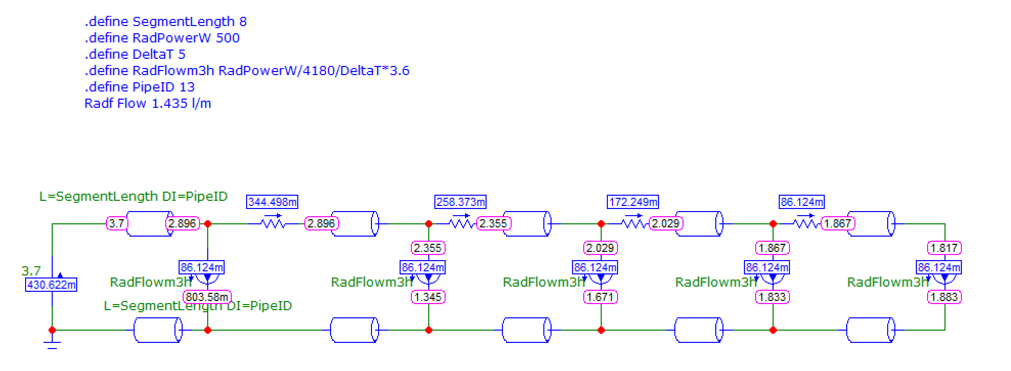
Assuming 5 rads, 8m pipe between rads (8m on flow and 8m on return) and 8m between airing cupboard and first rad, 13/15 copper pipe (power flushed).
500W per rad, deltaT 5, 1.4 l/min per rad, result is 3.7m pressure drop at the origin.
In other words, it works, barely, but it works at dT 5 which is very nice.
Most of the pressure drop is in the pipes close to the airing cupboard as these carry all the flow. Every time it branches to a rad, that rad takes some of the flow, so flow in the main pipes is lower, resulting in lower pressure drop. So you can't use the numbers for 40m of pipe with the full flow, as that would be quite pessimistic: it would model a scenario where all the rads are closed except the last one, and that shouldn't happen.
If the pipe runs in a circle around the house, then adding a pipe segment to complete the circle back to the airing cupboard divides the flow by 2 (half in the old pipe and half in the new), so it divides pressure drop by 4. In this case it works very well with a huge margin.
Will update if more accurate data is available.
At 50 years old your rads are likely full of nutella. That doesn't mean they're dead, but feeding sludge to a brand new heat pump will lead to an early death of the heat exchanger. Sludge also wrecks circulators. If you replace the rads with bigger ones, then great. With a thorough power flushing of the pipes, which is not hard to do, I don't see a reason why you'd have to rip your walls.

05/09/2026 3:32 pm
I'm not at all certain how long the 15mm pipes are that visit all of the radiators. A rough estimate would be to follow the perimeter walls around and visit every radiator in turn. If I do that, it adds up to 40m upstairs and another 40m downstairs. Thinking about this further, that must imply 80m of pipe in each case as the pipes are paired, with both flow and return all of the way around . Does that make sense? Would 80m for each 15mm pipe be a better (conservative) estimate to use here?
Heating pipes don't usually run around the perimeter of a house but forward and back (or side-to-side) from a central airing cupboard, with T-junctions off to one (or more) radiators. So a better estimate is to take the point where your 15mm pipes start and, using orthogonal distances, figure out which radiator is furthest from the start (remembering the vertical distances too). That will (probably) give your the index circuit, the one with highest resistance. It is possible that the longest one isn't the index if it has a small radiator and another slightly shorter one has a large radiator, then the shorter one would be the index circuit. And to calculate the pressure drop of this index circuit you'll need to calculate the pressure drop of each section, accounting for the flow dividing at each tee (T-junction). Some more fun measurements and calculations for you 😀
05/09/2026 3:53 pm
Some more fun measurements and calculations for you
... which hopefully you don't have to do if there is a reasonable amount of headroom! But if there isn't then fun awaits
I would be willing to bet that most installers don't bother in most cases. Easier to do some eyeball checks then fit and see what happens, with a backup plan in the relatively unlikely scenario that it doesn't work.
4kW peak of solar PV since 2011; EV and a 1930s house which has been partially renovated to improve its efficiency. 7kW Vaillant heat pump.
05/09/2026 4:07 pm
Some more fun measurements and calculations for you
... which hopefully you don't have to do if there is a reasonable amount of headroom! But if there isn't then fun awaits
I would be willing to bet that most installers don't bother in most cases. Easier to do some eyeball checks then fit and see what happens, with a backup plan in the relatively unlikely scenario that it doesn't work.
@rob-of-york is intending to put 3.7kW down some old 15mm copper and needing to use a dT of 7C to do it, so there isn't any headroom. TBH if I was him I'd get the some of the 15mm pipework replaced with 22mm so I could keep the dT at 5C and have some headroom.
I'd expect most installers would insist on replacing all/most of the distribution 15mm pipework to cover their posteriors!
05/09/2026 4:21 pm
@rob-of-york is intending to put 3.7kW down some old 15mm copper and needing to use a dT of 7C to do it, so there isn't any headroom. TBH if I was him I'd get the some of the 15mm pipework replaced with 22mm so I could keep the dT at 5C and have some headroom.
I would too if it were easy, but he says it isn't. In that circumstance I would probably 'suck it and see.'.
Assuming the circulator head is sufficient to operate at DT5, the viability of doing so will come down to noise. I don't know of a way to predict that and wouldn't be minded to sweat buckets before establishing that it's a problem. The extra effort of filling and, if necessary, draining down in order to run a test is negligible.
I'd expect most installers would insist on replacing all/most of the distribution 15mm pipework to cover their posteriors!
Some will for sure!
Some installers wanted to replace the 15mm cold water feed to my dhw tank. My mains pressure is 9bar and I get plenty of flow plus some at the most distant tap. To replace involves taking up half of the upstairs flooring. Those installers who insisted were politely shown the door (along with those who refused to acknowledge my measured heat loss).
This post was modified 1 month ago 11 times by JamesPa
4kW peak of solar PV since 2011; EV and a 1930s house which has been partially renovated to improve its efficiency. 7kW Vaillant heat pump.
Topic starter
05/09/2026 4:37 pm
Posted by @jamespa
There are a couple of possible installer parameters namely conf heat build pump, unit %pwm, default auto, but can be set 50%-100%
Thanks, if the 7kW heat pump can modulate down to 50% flow rate, then there is a good possibility that would work for me. 50% flow rate would be 0.167l/s and a dT of 10 at 7kW output.
Posted by @jamespa
Surely the drops to the radiators are in parallel not in series, so the index circuit for pressure drop calculations will be determined by the longest not the sum?
I don't think I described this very well. I was trying to figure out if the pipework is a single pipe or two pipe set up. If it was two pipe, i.e. separate flow and return around the perimeter, then it would be 40m out and back and so 80m on each floor.
I'm now convinced it is a two pipe set up, as we have TRVs and they work. But...
Posted by: @RobS
Heating pipes don't usually run around the perimeter of a house but forward and back (or side-to-side) from a central airing cupboard, with T-junctions off to one (or more) radiators.
So a better estimate is to take the point where your 15mm pipes start and, using orthogonal distances, figure out which radiator is furthest from the start (remembering the vertical distances too).
Thanks, unfortunately, I can see very little of where the pipework goes without moving furniture, pulling up carpet, sawing into floor boards and pulling them up, which I don't want to do.
Upstairs the index circuit is likely the radiator in the dormer bedroom. This radiator is about 8m orthogonal distance away from the airing cupboard where the pipework goes from 22mm to 15mm. It's also the largest upstairs radiator. Downstairs, the index circuit is likely the radiator at the end of the lounge. This radiator is about 13m orthogonal distance including vertical) from the pump and it is the largest one in the house. Unfortunately, I have no way of finding out how many junctions there are on the way to those radiators without ripping the floorboards up...
05/09/2026 4:37 pm
It would be nice to map the flow and return pipes and get some accurate lengths. Perhaps OP can discover a convenient way to split or loop the long 15mm run.
Hot pipes hidden in walls or below floors can be spotted with a thermal camera.
This post was modified 1 month ago by bobflux
05/09/2026 4:43 pm
Unfortunately, I have no way of finding out how many junctions there are on the way to those radiators without ripping the floorboards up...
Take a guess, do the head loss calculations at the flow rate for DT 5. If it's ok with some margin, stop worrying about head loss.
If this is the case it comes down to noise. Suck it and see is the only approach I know for this!
Perhaps OP can discover a convenient way to split or loop the long 15mm run.
That would be good but I think he has already said he can't find a convenient way.
This post was modified 1 month ago by JamesPa
4kW peak of solar PV since 2011; EV and a 1930s house which has been partially renovated to improve its efficiency. 7kW Vaillant heat pump.

SPONSORS

Degrees of Separation

Latest Posts
-

RE: Heat pump branding. Clever, contemporary… or a bit too much?
I think Heat Geek have done an amazing job on their bra...
By Tomtheheatingengineer , 3 hours ago
-
RE: HeatGeek vs Octopus surveys: puzzling disparity - any ideas why?
I have just had 3 heat loss surveys, one by heat geek o...
By David , 4 hours ago
-
RE: Heat Geek Zero Disrupt: Are We Sleepwalking Into Another Race to the Bottom?
I think that's the key question. After all inverter uni...
By Prunus , 5 hours ago
-
RE: battery storage without solar
As of October 1st they need specific qualifications to ...
By EtchedPixels , 6 hours ago
-
RE: How should the Boiler Upgrade Scheme be reformed?
A unit which uses water to transfer the heat/chill from...
By Temperature_Gradient , 6 hours ago
-
RE: Renewables & Heat Pumps in the News
With regards to the BUS grant raid, I gave it more thou...
By ASHP-BOBBA , 7 hours ago
-
RE: Why are ASHP installs so expensive?
The whole system seems to work on the basis of...
By ian33a , 7 hours ago
-
RE: Missing flow temperature in Heat Geek proposal
Good plan. If you can get half hourly meter readings a...
By JamesPa , 12 hours ago
-
RE: Heat Pumps Without Grants: Would You Have Installed One & Will You Now?
@editor Most certainly. The heat pump was an ideal s...
By Abernyte , 12 hours ago
-
Although regulations may well vary from country to coun...
By Majordennisbloodnok , 13 hours ago
-
RE: Does anyone have experience of a smart water meter?
Yep I caught our slow leak from a £100 bill rise 8)
By EtchedPixels , 13 hours ago
-
RE: Do You Need a Buffer Tank or Low Loss Header for Underfloor Heating in a Large Property?
@jamespa in some cases, failing the Turing test might b...
By GrahamF , 16 hours ago
-
RE: Passiv Smart Thermostat - Help & Forum Support
@energystoragetech The heat capacity of some...
By JamesPa , 18 hours ago
-
RE: tepeo ZEB UK Support & Info Thread
Sorry you are correct, I was remembering figures from t...
By JamesPa , 1 day ago




SPONSORS