

Notifications
Clear all
Joining the Renewable Heating Hub forums is completely free and only takes a minute. By registering you’ll be able to ask questions, join discussions, follow topics you’re interested in, bookmark useful threads and receive notifications when someone replies. Non-registered members also do not have access to our AI features. When choosing your username, please note that it cannot be changed later, so we recommend avoiding brand or product names. Before registering, please take a moment to read the Forum Rules & Terms of Use so we can keep the community helpful, respectful and informative for everyone. Thanks for joining!

Topic starter
15/06/2026 7:18 am
Looking for some advice - planning a self build - but at the early stages such that a lot of this hypothetical at the moment (we don't have exact floor plans) and therefore exact heat calcs.
However I am looking more for advice on the layout of the system.
It will be a house to PassivHaus standards, we will have a ASHP.
I will be running KNX throughout.
Looking at UFH with 10 loops in the concrete slab, and for the purpose of this lets assume all 10 loops are done in ridgeline eco max 22mm pipework, and have a length of 50m each (so 500m total, with a total water volume of 108L.)
The loops will all be controlled with Salus THB23031 auto balancing valves, and a UPM3 circulator pump.
The plan is to run this as an open loop, on 24/7, on WC. The auto balancing valves will throttle (or not) to maintain a deltaT across each individual loop (will not be zoning with them - all open all of the time).
ON top of this I will have a series of 7 fan coil units - for arguments sake lets say Dakin - FWF03DT.
My plan at the moment is to use these as trim heating or trim cooling. The FCUs will tee off the ASHP flow, have a zone valve, a magna1 circulator pump, split into 22mm pipe work for the runs, each FCU will have a PICV valve.
The exact strategy I have not yet worked out but anticipating something like this:
During heating season - UFH does the bulk of work on the WC, if the temp drops below setpoint -2, modulate PICV and FCU fan in that room to give some top up heating. I am anticipating this being unlikely during the winter in a passivhaus.
During the cooling season, as the heatpump hits the low end of the weather curve, switch into cooling mode. Run cooling at worst case dew point + 2. Apply a large moving average to this calc and only update every 5 mins or so (using KNX bridge to talk to ASHP) to avoid hunting and drastic changes.
Use UFH to cool the slab. if room with FCU is setpoint +2 modulate PICV valve and FCU fan. I anticipate this to happen more often, due to solar gain and the lack of efficiency cooling with a UFH slab.
I have been trying to do due diligence with the plumbing layout. I have had one ASHP with a buffer, and my most recent without.
I have read/watched plenty of information on the pro/cons of buffers volumisers etc. But have not been able to get my head around whether this is a case where I should be looking at them or not.
So assume worse case flow rate/volume for ASHP, as the system is above, plumbed direct.
This is FCU zone shut - all auto balance valves fully throttled (but importantly that is always CP -0.3mm on the stroke of the actuator). I have estimated this drops the flow rate per loop to around 0.6L/min [but this pure guessing?]. Giving a total flow of 6L/min in the system, and a volume of +108Ls.
Looking at valiant arotherm plus 5kW requirements (min flow 400L/h, min volume no back up heater 40l) I easily exceed the volume requirement, but I am below the 6.67L/min requirement (albeit only just).
I have ballparked guessed the 5kW for the passivhaus as I am not expecting big heating loads, this becomes even worse if I upsized to the 7kW (9l/min) or the 10kW (16.5L/min).
The other end of the spectrum, lets assume we have fully opened UFH valves, (relatively short loops, with a large, for UFH, diameter) we may achieve 30L/min on that loop. Lets assume that the 7 FCUs all turn on, so zone valve opens and PICVs start to modulate - for the FWF03DT, highest flow rate is 568L/h (heating) or 515L/h (cooling).
which gives 7 x 9.5L/min or another 66.5L/min.
Now I know the chance of all UFH zones being fully open, and the FCUs running full whack simultaneously is extremely unlikely - however I want to discuss the case as it is possible - the house has been empty for a while, we came back when it was truly cold and the heating had previously been off?? I don't know, but I want to understand what would happen hydraulically.
So this gives a total flow rate of 96L/min and a system volume in excess of 108L + FCU pipework/coils etc.
The volume is not an issue, but on the 5kW the max flow rate is 14.3L/min. on the 7Kw it is still only 20L/min.
Now even with more sensible assumptions I think the UFH could exceed or approach that on its own, and even if the FCUs were ticking over slowly, I think I would be way over the 20L/min.
Which brings me to the crux of my question - would a buffer be required? I appreciate distortion/mixing makes it normally a no/no. But hydraulically I think I am likely to be at the bottom end of the heat pump flow rate for the majority of the time (ie UFH is stable, nicely at temp, the balance valves will be mostly throttled, and assuming I will be in the region of around 6-10L/min) the FCUs however can demand a significant flow rate if they want. especially given that I am running them both cooler (for heating) and warmer (for cooling) than their design point.
Do I need the hydraulic separation that a 4P buffer provides, and if so is it worth going large, like say 200L to provide the ability for it to stratify?
Or another option I have looked at is including a 0-10V belimo ball valve as a bypass valve. Have a flow meter on the ASHP return with 0-10V output, and using KNX to proportionally open the bypass as the flow rate approaches the minimum ASHP requirement, which fixes the low flow rate issue, if I opened it at the other end of the scale, would it also fix the high flow rate issue. Obviously at the expense of efficiency, but only in the shoulder cases as it opens, and not permanently like a 4P buffer (with mixing/standing losses etc) would.
Another question I had, is there any disadvantages to having a 50L or so volumiser on the flow line, despite being above min volume, if I could absorb some of the cold water prior to the slab on defrost cycles, that seems like good thing.
Yes it would give me slightly more standing losses, and it would add a lag into the system, but for an open loop 24/7 WC plan, I don't see this being an issue in a passivhaus?
Sorry for the long post, if you have any more questions just ask, I know some of this is over engineered, but I do enjoy that side of it as well!

15/06/2026 1:12 pm
My first question is why bother with the auto balancing valves, what value are they adding (other than to confuse matters). Why not just normal manual flow control valves, balanced once manually then left
The flow rate from the ashp (and thus to the emitters unless you have a buffer) is determined by the ASHP pump. So long as its sufficient to carry the heat required - which it will be if the pipes are large enough and the emitters tolerably well balanced, why are you worrying about it at all?
Personally I would avoid a buffer if I possibly could, it will just make things more complicated and cost money. A volumiser will do no harm.
I think you may are very probably over engineering, but if there is a solid reason for the additional components then maybe not. Perhaps a diagram may make things clearer.
This post was modified 4 months ago 2 times by JamesPa
4kW peak of solar PV since 2011; EV and a 1930s house which has been partially renovated to improve its efficiency. 7kW Vaillant heat pump.
Topic starter
15/06/2026 7:50 pm
Thank you for the reply
So in answer to your first question: I like the concept of the auto balancing valves. And that they strive to maintain the delta T regardless of environment for the loop, rather than commissioning at one snapshot in time and hoping that leaves the zones balanced regardless of external factors.
But on to why I am worrying about it, great question, with the auto valves or manual, I was under the impression that with multiple pumps (the ASHP internal, the FCU pump, and the UFH manifold) I need to be careful so that they do not 'fight' each other.
I was going to run the UFH and FCU pump in CP mode, and I know the ASHP will modulate itself, my concern was the extremes of flow rate I think my system may see. And if this will cause issues for the ASHP. Ie the low flow case of no FCUs and a slab that is just ticking over to maintain temp. And the high flow case of FCUs and a slab that is coming back up to temp.
From my research so far, I would also like to avoid the buffer, but I also am trying to back up my decisions with knowledge. I guess that my (one of many) gap in knowledge at the moment is, do I need a low loss header (as essentially that is what the buffer is providing for me?) And if not, why not, as in my head I have both a minimum and maximum possible flow rate outside of the ASHP published limits.
Which is what then led me down the garden path of looking at proportional bypass valves
15/06/2026 8:02 pm
. And that they strive to maintain the delta T regardless of environment for the loop,
Why do you want to maintain a specific deltaT? The output of the emitter (which is what you really care about, because it needs to balance the heat loss) is essentially dependent on the flow temperature (which is set by the heat pump). Delta T is (to first order) a consequence of that.
But on to why I am worrying about it, great question, with the auto valves or manual, I was under the impression that with multiple pumps (the ASHP internal, the FCU pump, and the UFH manifold) I need to be careful so that they do not 'fight' each other.
You are right they will (or at least may) fight, but why do you want multiple pumps in the first place? Why not one pump pushing water through the system.
Whats the floor area of your house?
The basics are that you need to transport 5kW (at peak demand) from heat pump to emitters. Unless you have incredibly long runs of standard pipe or very long runs of of microbore this is easily done at a sensible flow flow rate with any standard circulator pump and a deltaT of 5 or less. 5 or less is a sensible value and if it turns out to be less, then so much the better (so long as its not too much less, because then you are wasting water pump energy for no good reason and would be better off slowing the pump down - but not imposing flow restriction).
Once it has got to the emitters it will transfer to the room at a rate principally dependent on the flow temperature, and only secondarily on the delta T (its generally best to think of deltaT as dependent on other factors not driving other factors, although increasing it by throttling flow is a good way to reduce output and redirect it elsewhere - thats balancing!).
So what you principally care about is the flow temperature in relation to the demand, not the deltaT in relation to the demand. I think you may be trying to control the wrong variable by restricting flow unnecessarily.
This post was modified 4 months ago 9 times by JamesPa
4kW peak of solar PV since 2011; EV and a 1930s house which has been partially renovated to improve its efficiency. 7kW Vaillant heat pump.


16/06/2026 11:49 am
Hi
I'll skip the feedback sandwich 😉
UFH corrugated stainless steel pipe - looks horribly expensive but if money is not an issue then no problem. Your other option is 16mm MLC pipe, which is much cheaper, stiffer and more fiddly to lay, and has much higher pressure drop. There is also 20mm barrier PEX but it's a bit of a low end option. Anyway, UFH is all about flow and pipe spacing, so I have to ask about what the pipe spacing is. If it is more than 150mm, especially 200mm, then switching to 16mm MLC pipe (13mm ID) with much closer spacing (100mm) will have better heat diffusion and pretty much the same flow if loops are short enough (50m is good).
The criteria for UFH loop length is: can you get 1m/s in the pipes with the circulator at max speed and only one loop open? If not, you need to hook up a pump to flush bubbles and that's damn annoying. Note most UFH manifolds have Kv=1 control valves so do not meet this requirement.
Auto balancing valves: useless, and limited life time due to wax motor. If you use a heat pump in weather compensation mode, flow temperature is variable and deltaT is also variable. I mean, you can configure the heat pump so it'll control its circulator speed for constant deltaT but this may not work and is less efficient because it is equivalent to a higher flow temp, and it probably won't work also.
There are subtleties about ultra low temperature UFH like you plan to install. Consider this: flow/return temps in my UFH are around 24/22°C and the room is 21°C. If I configure the thing for 5°C deltaT it's not going to work at all, because return can't be lower than core clab temp. So it has to operate at very low deltaT when running at low power. Then at full power deltaT increases. This means auto balancing valves which expect to work on constant deltaT would not work at all. Also if an UFH is well designed with good transfer from pipe to slab, higher deltaT means less uniform floor temperature, so it's better to increase flow and reduce deltaT. Make sure to oversize the primary pipes.
Fan coils for heating: no need, your UFH is already over designed for the house. Unless you skimped on the pipe spacing because the 500m reel costs 4000€, in which case put twice as much 16mm MLC instead, problem solved.
Fan coils for cooling with water above the dew point: useless.
Slab for cooling with water above the dew point: better than nothing, but really meh.
Fan coils for cooling with water below the dew point (5°C): absolutely excellent, but you need all the piping to be vapor tight insulated to avoid condensation, and valves to make sure no cold water gets in the wrong place, especially in the slabs.
Cooling with water below the dew point removes humidity from the air, which makes summer a lot more comfortable. Cooling with water above the dew point does not remove humidity from the air, and by cooling hot moist air, relative humidity increases, so it is not comfortable. It feels cool, but you still sweat buckets.
PICVs for fan coils: useless. They will screw up your controls, lower your output, and trigger flow errors on the heat pump.
Two extra circulators: not needed, they will conflict with the heat pump's internal circulator, and you will need a buffer/low loss header with associated problems. Also the buffer will be filled with cold water in summer, which means it also needs to be vapor tight insulated. It's a nightmare. Also, a MAGNA for a 5kW heat pump, seriously? If you needed an extra circulator, which you don't, a 100€ Alpha 1L would be more than enough, and it has remote controllable speed too.
So you need motorized valves and routing between HP / hot water tank / FCUs / slabs to avoid sending water at the wrong temperature in the wrong place.
Solution:
Summer mode: direct from heat pump to FCUs. Use zone valves for on/off, modulate fan speed for temperature control. Your FCUs have ESC motors with remote control fan speed, right? I use Panasonic FD30's they have 0-10V remote fan speed control. In your home automation programming, ensure enough zone valves are open to meet the heat pump's minimum flow, otherwise open some valves or turn it off, then modulate fan speed. If less FCUs have their zone valve open, they'll just get more flow, which is good. If minimum flow is not met, it's okay to open some FCUs without actually turning on the fan. This will cause mixing, distortion, and lower heat pump efficiency. Due to photovoltaics, when cooling is needed, electricity is free, so optimizing heat pump efficiency in summer is completely irrelevant. The only important things are flow, raw power, and to get the water to the FCUs at low enough temperature without the heat pump's regulation screwing things up.
Winter mode: direct from heat pump to slabs, run weather comp open loop. Balance each loop manually, then you can add zone valves, but they should not be necessary. You can also use the FCUs if you want.
> Now I know the chance of all UFH zones being fully open, and the FCUs running full whack simultaneously is extremely unlikely - however I want to discuss the case as it is possible - the house has been empty for a while
Pick up your phone the day before you come back from vacation, open home assistant, set thermostat temperature, return to warm home.
If you plan a 5kW heat pump it's not going to heat the house fast no matter what the emitters are.
Once you try FCUs cooling with really cold water I'll bet a beer you replace the 5kW HP with the biggest one you can find and only look at the cooling numbers in the datasheet lol
2

16/06/2026 12:18 pm
I was under the impression that with multiple pumps (the ASHP internal, the FCU pump, and the UFH manifold) I need to be careful so that they do not 'fight' each other.
1: Why are you thinking there would be a pump on an UFH Manifold?
Manifold pumps would usually only be present if that manifold is running in a mixer-mode, to reduce the temperature of the incoming water by mixing it with water from the Return side.
Your incoming water won't be too hot to send it through the UFH pipes.
UFH 'works' by radiating Far Infra Red radiation (photons), which is why it feels more comfortable to the human body than the room's physical air temperature would suggest. The lower is the water temperature, you get less FIR radiation, and more direct heating of the floor pad. That's using conduction to heat the air.
The basic strategy is to keep the home comfortable for occupation by humans, rather than employing maths to save a few Joules.
2: As this is to be PassivHaus, please clarify what ventilation system you expect to use?
Do you have any intention to double-use that airflow for heating/cooling in summer/winter?
Or will it be entirely separate?
You may have not considered ventilation yet, which is fine.
I just wanted to pop the question in before you spend too much time doing heating calculations!
3: Please confirm:
Is this hypothetical house for single occupancy?
Or is the system under discussion intended for two or more independently habitable spaces?
Save energy... recycle electrons!
Topic starter
16/06/2026 8:48 pm
Thank you for the replies - this is exactly what I was hoping for at this time!
Okay so consensus is bin of the auto balancing valves. Happy.
The UFH heating pump, now that is a hangover for how I did it previously when I did have a blending valve, but if the ASHP pump is good enough to push it round 10 x loops of
50m. I can get rid of that too. That leads me to ask do I need one of those preformed UFH manifolds, or can I do a series of tees to 3/4 BSP M connectors? I can get the ancillaries (fill valves, vents etc) and build one myself essentially?
@bobflux Happy for you not to pull any punches, it will end up with me having a better design!
The ridgeline pipework - agreed it is more expensive, I like it for the larger bore size, and the fact it is easier to install (I want to do as much of this myself as possible). Money is less of a concern for elements like this (at this point anyway!)
Okay good to hear about fan coil cooling with water temp above dew point - I had toyed with being below but thought I may save myself potential condensation issues, but if it is not worth the time I can go back to no slab cooling, and just fan coils at low temp with vapour sealing on all cold pipework.
Have you found any condensation issues on things like your dirt filters that I imagine are hard to vapour seal?
Please can you expand on why PICVs are useless? My intent was to use a 0-10v actuator on them as well as the FCUs ESC fan, controlled by a Zennio KNX product (MiniBox 0-10V x2) that modulates both - and has a dedicated module that is designed for modulating both.
In my head the PICV is just a slightly more fancy individual zone valve, that caps it at a set max flow rate, but allows me to modulate below that? So I could still open it up (via KNX) and pass water through without turning the fan on etc to avoid minimum flow rate issues.
I was thinking of the smallest Magna1, tbf to myself! But I was under the impression that FCUs can require quite a high flow rate? Will the ASHP pump be able to cope with them at full tilt if required? If so I could drop both this extra pump as well as the UFH pump! However even if I do size up the ASHP, the maximum flow rate on the valiant data sheet is still below 7 x FCU data sheet flow rate for cooling on high, by a significant margin - is this going to cause problems?
Your solution plan in terms of summer/winter is what I started at before talking myself down a garden path! But I feel like now I have travelled I have slightly more understanding about why this is a better route.
HA is to be my front end, plenty of time spent tinkering with that in my last property.
1: As above, I am with you now.
2: I have not looked in detail at the MVHR yet, broadbrush was looking at a Zehnder ComfoAir, and keeping it entirely for ventilation.
3: The plan is a 4 bed barn style house - we currently work and live abroad, and it is our return to the UK family home! Hence why this is a hypothetical at the moment - I have some rough plans, but for example we are currently putting an offer in on a plot of land. So we have a long way on this journey yet!
16/06/2026 9:07 pm
But I was under the impression that FCUs can require quite a high flow rate?
Im not sure they will in your case? FCUs are just like any other emitter, the energy they will emit is dependent principally on the flow temperature (and of course fan speed). The energy they need to emit is determined by the house not the spec of the FCUs. You arent wanting 2kW out of each of your FCUs because the house doesn't need that much heat! We know that the total for the whole house is 5kW = 13l/min at DT5, or if you want to reduce DT to say 2.5 (as @bobflux rightly suggests you might) 26l/min. That then gets distributed to the various emitters.
In principle you need to do the equivalent calcs for cooling, or just suck it and see given the relatively low proportion of days in the UK where its necessary.
but if the ASHP pump is good enough to push it round 10 x loops of 50m.
Dont forget that the loops are in parallel not in series so that makes it easier to get the total flow you need not less easy.
This post was modified 4 months ago 5 times by JamesPa
4kW peak of solar PV since 2011; EV and a 1930s house which has been partially renovated to improve its efficiency. 7kW Vaillant heat pump.

16/06/2026 9:20 pm
Ah... a family home.
OK, I'm starting to get the picture.
Just how much self-build are you intending?
Is this to be hands-on by you and the family?
Or will you be using contractors for some of the work?
As a hands-on self-builder myself, I well aware that this makes a difference to the way in which you approach the selection of build-style and the phases of construction,
We can adjust our answers to you depending on which 'trades' you'd like to do yourself.
Save energy... recycle electrons!
Topic starter
16/06/2026 10:07 pm
@transparent Contractors for elements, I like being hands on for as much as possible - I have got enough sparkie qualifications that I am happy to do the wiring myself.
I would like to do as much of the plumbing as I can myself - I do not have any qualifications so can not do any of the G3 stuff, but if I can get all the fittings to the tank and have a plumber friend come in and make sure everything is above board and connect it up.
I would like to also do the MVHR as well.
But I know my limits - plastering, finishing and items that are on show are probably best left to people with refined skills!
@jamespa Okay that is a better way for me to think about it - makes sense.
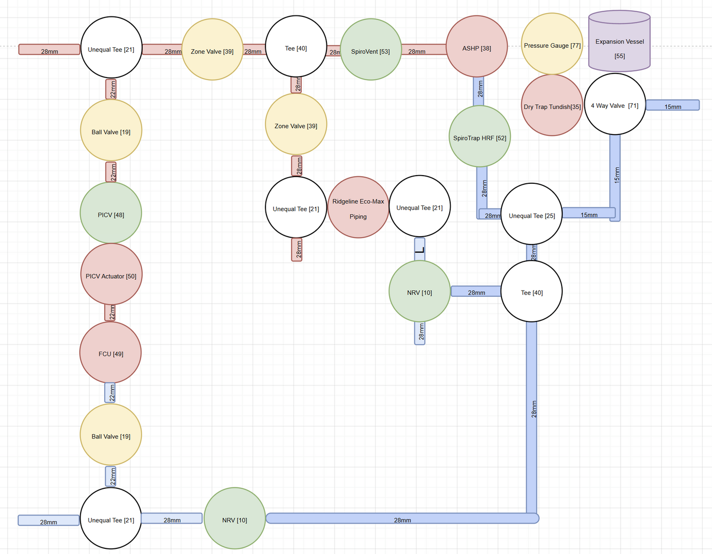
So I don't know how that will display on the forum, but essentially I have got the ASHP, 28mm pipe through a spirovent, then splits at a tee -> zone valves on both legs.
FCU side then tees to 22mm for each FCU (only one displayed for ease). Each leg has a ball valve, a PICV valve (and actuator) [pending further discussions as above], a FCU, a ball valve, teed back to 28mm for return, via a NRV. Back to ASHP.
The UFH leg will have tees for 3/4 BSP M -> ridgleine Eco pipe -> tee back to 28mm -> NRV. Back to ASHP. Only one loop shown for ease. Not shown is a ball valve to isolate before the "tee manifold" on flow and on return. and probably a filling/drain valve.
On the ASHP return is via a spirotrap, included is the expansion vessel which goes off to filling loop.
I have dropped both the FCU circulator pump, and the UFH manifold pump, the pre made manifold itself, and the auto balance valves. I need to add back in some manual valves so I can commission it
This post was modified 4 months ago 2 times by chastity_outward053@simplelogi
17/06/2026 8:45 am
@bobflux Happy for you not to pull any punches
Not my style 🤣 🤣
The installation you're planning looks like the one I'm building (FCUs + UFH) except I'm adding a wood furnace which adds substantial complexity. So I've done all the research but it's not built yet, I can share the R&D and experience from the old installation but obviously not experience from the new one!
The UFH heating pump, now that is a hangover for how I did it previously when I did have a blending valve, but if the ASHP pump is good enough to push it round 10 x loops of 50m. I can get rid of that too.
Power & Flow
Power (W) = [Flow rate] * [ DeltaT ] * [Heat capacity ] thus for water, Power (W) = [Flow in l/s] * [ DeltaT in °C ] * [4180 J/l/°C ]
changing units: P = [Flow in l/min] * [ DeltaT in °C ] * 70
[Flow in l/min] = Power / ( [ DeltaT in °C ] * 70 )
So 5kW deltaT 5°C gives 14 l/min, but it you want ultra low temperature UFH with deltaT 3°C, maybe aim for 25 l/min.
Pressure drop
I have entered the equations in this LibreOffice spreadsheet (have to enable macros when loading it) so if you fill in the three slots outlined in yellow (flow rate, pipe internal diameter, length) it will give you pressure drop.
In a pressurized closed circuit without air bubbles, what matters is pressure drop not length or geometry. Pressure drop is proportional to:
- Pipe Length
- Flow squared
- Pipe internal diameter to the power of about 5
Flow squared means if the pipe is too small and you don't get enough flow then there's not much you can do, so it's important to size the pipes properly. You can find the flow vs pressure drop graph of the heat pump circulator in the manual. Note a circulator has a finite power budget which comes from its electrical power consumption, thus if you ask for more pressure you get less flow, you trade one for the other. Here's Grundfos Alpha 1L, which I like, because it is absolutely silent, lasts forever, has remote control speed, and is available for 100€ "used brand new in unopened box".
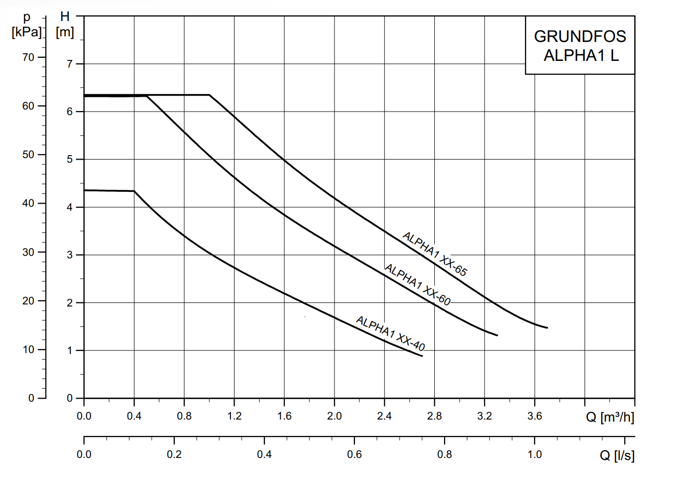
How to read this curve: at flow rate Q (horizontal axis) the curve gives the maximum pressure drop it can generate with 100% speed (vertical axis). If you know the pressure drop vs flow curve of your system, the operating point will be at the intersection.
If you want more pressure and more flow at the same time you need a bigger circulator which will use more power. Since your 5kW heat pump is going to run at excellent COP on your low temperature system, it will probably draw 300-1000W depending on modulation, so adding a 200W circulator will completely wreck your COP. Modern heat pumps have become so optimized that power consumption from circulators can significantly worsen the total energy use... that's why they all have variable speed pumps these days...
You only pay for the pipes once, and most of the expense is not in the pipe itself but in the work to install it anyway, but if the pipe is too small you pay more in electricity forever to push water through it.
Hence it is super important to get the flow & pressure drop calculations correct, or at least to err on the size of "too big".
Now for your UFH loops, you can decide the minimum umber of loops you want open (say 5), split the flow (25 l/min in 5 loops so 5 l/min per loop), use the spreadsheet, and aim for 1000-2000 mmH2O (0.1-0.2 bar) pressure drop. Then you can see your 22mm corrugated pipe (assuming 18mm inner diameter) is wayyyyy more than enough and you will have no problems whatsoever even with only half the loops open. In fact it would probably work fine with 16mm MLC pipe with more zones open.
That leads me to ask do I need one of those preformed UFH manifolds, or can I do a series of tees to 3/4 BSP M connectors? I can get the ancillaries (fill valves, vents etc) and build one myself essentially?
Whatever you want. UFH manifolds are glorified tees with gold plated prices. Just a convenient way to quickly install it, with valves etc already fitted.
Per-loop flowmeters are nice for balancing though, but keep pressure drop in mind. For example consider Caleffi 6716 UFH manifold: flow adjustment valves have Kv=1
Kv is the flow rate in m3/h with pressure drop 1 bar (10 mH20), thus (pressure drop in bar) = ((Flow in m3/h) / Kv)^2
Kv is a convenient way to express the pressure drop in an element. Higher Kv means higher flow at the same pressure drop or lower pressure drop at the same flow.
You can also write the pressure drop of a pipe as a Kv: Kv = (Flow in m3/h) / sqrt(pressure drop in bar).
Your 50m corrugated 22mm pipe equals Kv about 1.5. On Caleffi 6716 manifold a fully open loop balancing valve has Kv=1. Which means you get more pressure drop in the valve than you do in the pipe. In this case, the valve will have great authority to control flow, but the expensive pipe is a waste of money because the high flow allowed by its large diameter is restricted by the valve, even fully open. These manifolds are meant for 16mm MLC pipe, in this case the pipe has a bit more pressure drop than the fully open valve, and the valve still has good authority, so it's a good match.
On UFH manifolds the other loop valves with the knobs, where you screw the thermoelectric actuator heads, tend to be on/off only. They certainly are on mine, and thermoelectric actuators are also on/off only. IMO not useful for a heat pump in weather compensation mode.
Note: valve authority is a measure of how well it can control flow. For good authority you want the valve (not the loop) to control the pressure drop (thus the flow). For example, if you use a full bore 3/4" ball valve (Kv=26) to control flow in a UFH loop (Kv=1.5) the valve will only begin to restrict flow when it is almost completely closed, and the angle range on the handle which actually controls flow rather than being "almost fully open" will be so tiny to be completely unusable. However, a partial bore 1/2" ball valve (Kv= about 3.5) would begin to control flow around about half closed so it is usable. That's why they build manifolds with Kv=1 balancing valves. Basically big ball valves are strictly on/off only, they are all about NOT restricting flow, which is why you're supposed to mount a ball valve of the same pipe diameter as the pipe, so when open the inside of the pipe is completely unrestricted and smooth through the valve. Whereas flow control is all about restricting flow in a controlled manner, for this you need either a valve designed for it (radiator TRV for example) or a ball valve that looks about two sizes too small.
Going to paint my ceiling, will answer the rest later.
1
17/06/2026 9:05 am
@chastity_outward053simplelogi
Diagram looks unduly complex to me but @bobflux will likely suggest mods so I wont comment further other than to say that the application of occams razor to any ASHP system is strongly advised. Basically what you need is an ashp, a diverter valve, a detritus filter or two, an expansion valve, pressure gauge and filler loop and emitters that you can balance on manual valves that ideally have good valve authority. Add in any isolation valves you see fit and if you wish a pair of antifreeze valves. Everything else is probably surplus to requirements.
4kW peak of solar PV since 2011; EV and a 1930s house which has been partially renovated to improve its efficiency. 7kW Vaillant heat pump.
Page 1 / 4
Next
SPONSORS

Degrees of Separation

Latest Posts
-

RE: Heat pump branding. Clever, contemporary… or a bit too much?
I think Heat Geek have done an amazing job on their bra...
By Tomtheheatingengineer , 4 hours ago
-
RE: HeatGeek vs Octopus surveys: puzzling disparity - any ideas why?
I have just had 3 heat loss surveys, one by heat geek o...
By David , 5 hours ago
-
RE: Heat Geek Zero Disrupt: Are We Sleepwalking Into Another Race to the Bottom?
I think that's the key question. After all inverter uni...
By Prunus , 6 hours ago
-
RE: battery storage without solar
As of October 1st they need specific qualifications to ...
By EtchedPixels , 7 hours ago
-
RE: How should the Boiler Upgrade Scheme be reformed?
A unit which uses water to transfer the heat/chill from...
By Temperature_Gradient , 7 hours ago
-
RE: Renewables & Heat Pumps in the News
With regards to the BUS grant raid, I gave it more thou...
By ASHP-BOBBA , 8 hours ago
-
RE: Why are ASHP installs so expensive?
The whole system seems to work on the basis of...
By ian33a , 8 hours ago
-
RE: Missing flow temperature in Heat Geek proposal
Good plan. If you can get half hourly meter readings a...
By JamesPa , 13 hours ago
-
RE: Heat Pumps Without Grants: Would You Have Installed One & Will You Now?
@editor Most certainly. The heat pump was an ideal s...
By Abernyte , 13 hours ago
-
Although regulations may well vary from country to coun...
By Majordennisbloodnok , 14 hours ago
-
RE: Does anyone have experience of a smart water meter?
Yep I caught our slow leak from a £100 bill rise 8)
By EtchedPixels , 14 hours ago
-
RE: Do You Need a Buffer Tank or Low Loss Header for Underfloor Heating in a Large Property?
@jamespa in some cases, failing the Turing test might b...
By GrahamF , 17 hours ago
-
RE: Passiv Smart Thermostat - Help & Forum Support
@energystoragetech The heat capacity of some...
By JamesPa , 19 hours ago
-
RE: tepeo ZEB UK Support & Info Thread
Sorry you are correct, I was remembering figures from t...
By JamesPa , 1 day ago




SPONSORS
