Joining the Renewable Heating Hub forums is completely free and only takes a minute. By registering you’ll be able to ask questions, join discussions, follow topics you’re interested in, bookmark useful threads and receive notifications when someone replies. Non-registered members also do not have access to our AI features. When choosing your username, please note that it cannot be changed later, so we recommend avoiding brand or product names. Before registering, please take a moment to read the Forum Rules & Terms of Use so we can keep the community helpful, respectful and informative for everyone. Thanks for joining!
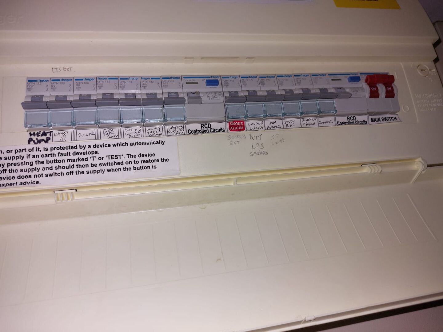
My son has a house that was fully rewired in 2015 with a CU that included 2 RCDs & MCBs
A recent install of Powerwall (with Gateway) with PV Solar was apparently successful but unfortunately not tested for grid outage.
Subsequently power cuts and tests tripped one of the RCDs every time. It would not reset without a full powerdown of Powerwall. Obviously giving less resilience than before.
Investigations by installer said initially there was a earthing fault but now says that the RCD is the problem. They say replacing the RCD might cure the problem - but no certainty longer term.
They recommend a complete replacement of CU (with RCBOs etc).
Somewhat disappointing that the issue was not found earlier - at least with an initial test. However the main thing is to resolve the issue.
Do installers/electricians agree with the diagnosis and proposed solution?
I have asked the installer for a written report so that I can pass to electrician - but not received yet.
Listed Grade 2 building with large modern extension. LG Therma V 16kw ASHP Underfloor heating + Rads 8.7kw pv solar 3 x 8.2kw GivEnergy batteries 1 x GivEnergy Gen1 hybrid 5.0kw inverter Manual changeover EPS MG4 EV
They recommend a complete replacement of CU (with RCBOs etc).
I am not familiar with the powerwall inverter but when converting to DC it may cause some DC currents to flow upstream like other inverters. Difficult to say without having all the details at hand.
When you state you have two RCDs this tells me that they are shared across multiple circuits, which is not ideal, specially when supplying inverters. So changing that to a modern RCBO based fuseboard will allow better isolation of faults and also enable supplying the inverter via its own circuit, allowing changes, for example to the inverter RCBO type or curve to be made without impacting other circuits.
Another thing to also consider is having SPD protection on the board. I believe this is not mandatory in all types of dwellings, but the % added cost (specially when considering labour) is minimal.
So while the board change may not resolve your son's issue, it seems a sensible first step. Another option that comes to mind would be fitting a small dedicated unit to connect the powerwall.
8kW Solis S6-EH1P8K-L-PLUS hybrid inverter; G99: 8kW export; 16kWh Seplos Fogstar battery; Ohme Home Pro EV charger; Vaillant Arotherm Pro 7kW; 100Amp head, HA lab on mini PC
and by now you should be able to guess what I'm about to say:
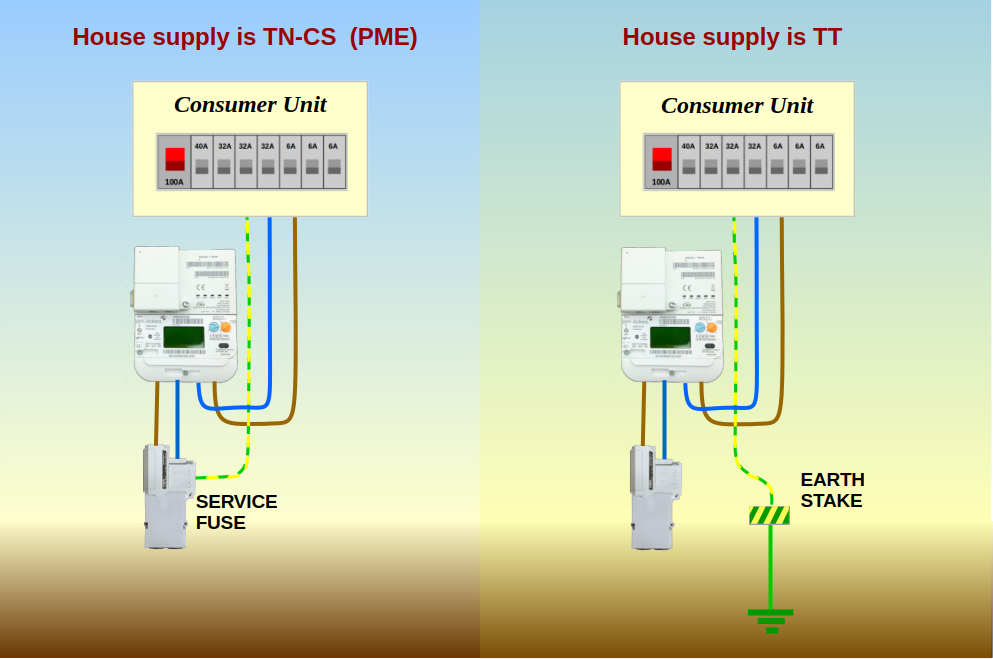
What type of electricity supply does the house have?
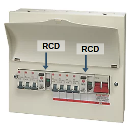
The Consumer Unit you describe is called Split Load.
Some of the household circuits are fed via one of the RCDs, and the rest are supplied by the other.
In the event of an earth-leakage fault on one circuit only its RCDs will respond and cut power. So if you've got a sensible division of circuits between the two RCDs then you should have some lighting circuits and some power circuits still working. That means you can see how to fix the fault because the whole house hasn't been plunged into darkness.
All electrical circuits in the home will have a small amount of leakage. There's no such thing as a perfect insulator.
The RCD will only trip when that leakage current reaches the designated threshold, which is usually 30mA. That's 30mA of current which is being supplied via the live conductor, but not returning on the Neutral wire.
If the circuits supplied one RCB already have 26mA of leakage, and a new circuit is added (a Powerwall) which has 10mA of leakage when first switched on (following a power-cut), then the RCD should trip.
The usual approach is to fit an entirely new RCBO to connect the Powerwall, which is supplied only by the large red Main Switch in the Consumer Unit. Since it isn't connected via either of the two existing RCDs, it starts its life by having zero earth leakage.
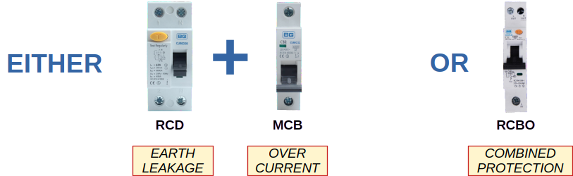
The RCBO provides protection for both over-current and earth-leakage faults.
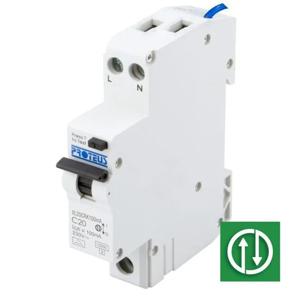
Since the Tesla Powerwall is a storage battery, it can pass current in either direction along its connecting wire.
So the type of trip you require is a Bi-directional RCBO. Moreover, if it's on its own dedicated cable from the Consumer Unit, then the earth-leakage specification of the RCBO can be greater than 30mA.
Here's a UK-manufactured bi-directional RCBO with 100mA earth-leakage rating. That's adequate to provide protection against fire and animals damaging the cable.
It's labelled C20. That allows 20A of current to pass, but the C-curve rating means it will act slower than the more common B-curve. I use C-curve trips for circuits which have a high in-rush current when an appliance is switched on.
Thus my workshop which has a table-saw and welding machine is fed from a C-curve breaker.
Listed Grade 2 building with large modern extension. LG Therma V 16kw ASHP Underfloor heating + Rads 8.7kw pv solar 3 x 8.2kw GivEnergy batteries 1 x GivEnergy Gen1 hybrid 5.0kw inverter Manual changeover EPS MG4 EV
I wouldn't recommend changing either the RCDs or the entire CU at this stage.
That would make it even more difficult to diagnose the fault if the Powerwall continued to cause tripping.
Take one step at a time, by simply using a separate bi-directional RCBO for the Powerwall supply... ... and remember, the rest of us are working blind here. We don't even know if there's physical space for an RCBO to be added.
Listed Grade 2 building with large modern extension. LG Therma V 16kw ASHP Underfloor heating + Rads 8.7kw pv solar 3 x 8.2kw GivEnergy batteries 1 x GivEnergy Gen1 hybrid 5.0kw inverter Manual changeover EPS MG4 EV
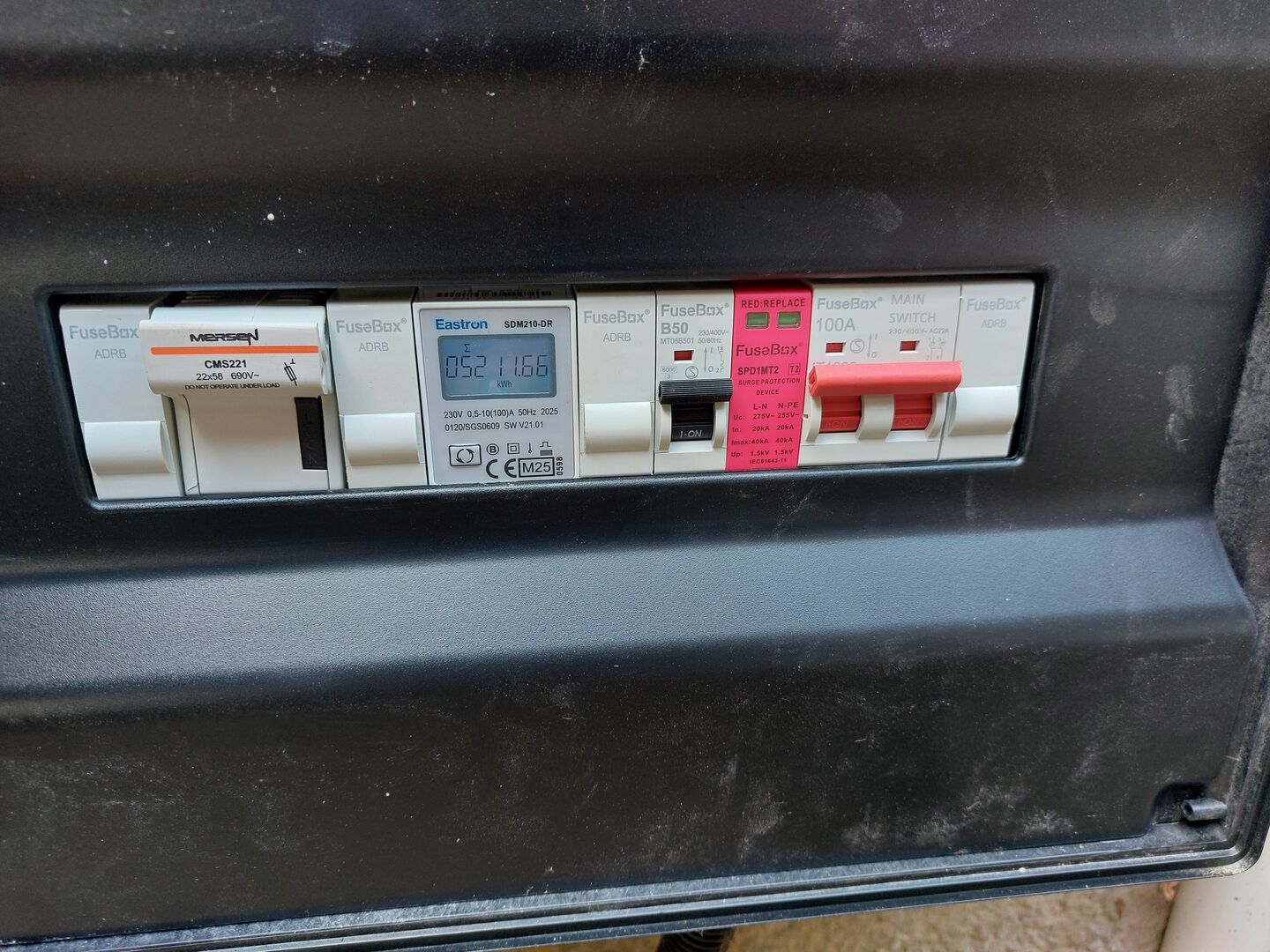
I'm sure @transparent will give you a more qualified answer, but I would expect to see either (i) an RCBO, or (ii) a MCB and an RCD (which when combined provide the same functionality as an RCBO) in the Gateway.
You appear to only have an MCB (the B50 device) and no RCD. In my Gateway I have both MCB (B63) and an 80A dual pole RCD.
I would also think the B50 50A MCB is cutting things a little close as the PW3 is a 48A device. I think a 63A MCB allows a little tolerance / head room.
This post was modified 3 months ago 3 times by Old_Scientist
Samsung 12kW gen6 ASHP with 50L volumiser and large radiators. 7.2kWp solar (south facing), Tesla PW3 (13.5kW). Net Zero
Listed Grade 2 building with large modern extension. LG Therma V 16kw ASHP Underfloor heating + Rads 8.7kw pv solar 3 x 8.2kw GivEnergy batteries 1 x GivEnergy Gen1 hybrid 5.0kw inverter Manual changeover EPS MG4 EV
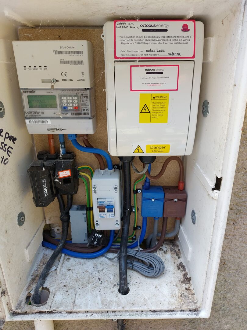
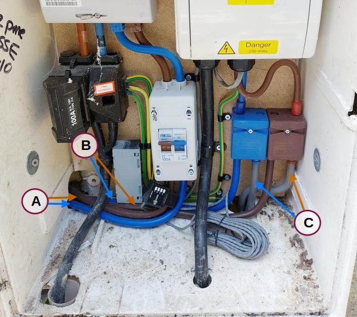
I've labelled three pairs of double-insulated tails.
Pair-A go from the central Switch Disconnector to something... possibly the main house Consumer Unit.
Pair-B return from that something and go to the pretty Henly Blocks on the right.
The Zappi EV Charger is supplied from the top of those Henly Blocks.
Pair-C go to something else, which I assume is the Black DIN Enclosure you're calling a Tesla Gateway.
Please confirm if I've correctly identified those three Pairs.
Then tell us what's in that light grey PVC enclosure next to the three earth wires.
2: The Tesla Gateway has four spare ways on the DIN rail. They have blanking covers marked ADRB.
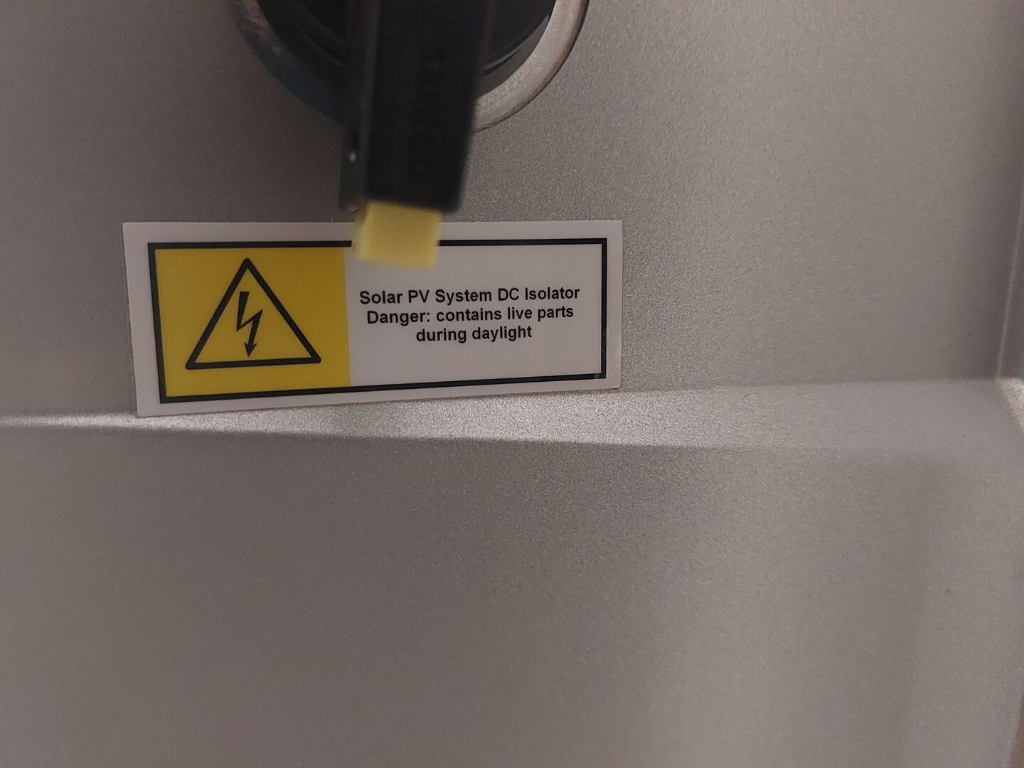
I'll assume that the incoming wires from the rooftop solar panels go to the Mersen fuse-carrier. This is labelled Do not operate under load, which we assume means Do not open under load... .. but there's no DC isolator present which would allow you to remove the load.
This black box needs a label to say where there's a PV isolator switch.
3: The Tesla gateway has a 2-pole surge protection device for the mains... ... but no lightning protector for the rooftop panels. Hmmm.
The SPD is connected to the mains internally, presumably by thick wires from the adjacent Main Switch. It also needs a good thick earth wire to take surges away to ground.
However, it looks like its earth connection goes back to the 100A Service Fuse, and thence to the Neutral connection on the house supply.
That won't work. It's a circle.
There should be a hefty earth stake to receive the 20,000A of surge and send it directly into the ground.
The SPD is there to provide protection against a nearby lightning strike which travels into the house via the DNO's incomer. Ie the surge is arriving via the Live and Neutral simultaneously (known as common-mode), and your SPD is trying to send it back to the Neutral, which also acts as your earth!
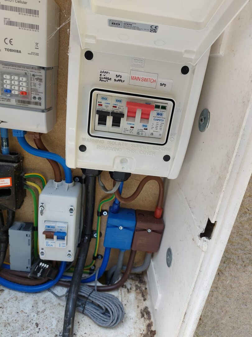
4: The SPD in your Zappi connection box won't work either.
It's rated for 40,000A but someone has helpfully connected it via a 32A MCB trip to prevent it being damaged!
The SPD is meant to take the damage. That's how it protects your Zappi !
The MCB is completely useless anyway because it operates far too slowly to handle an incoming lightning surge.
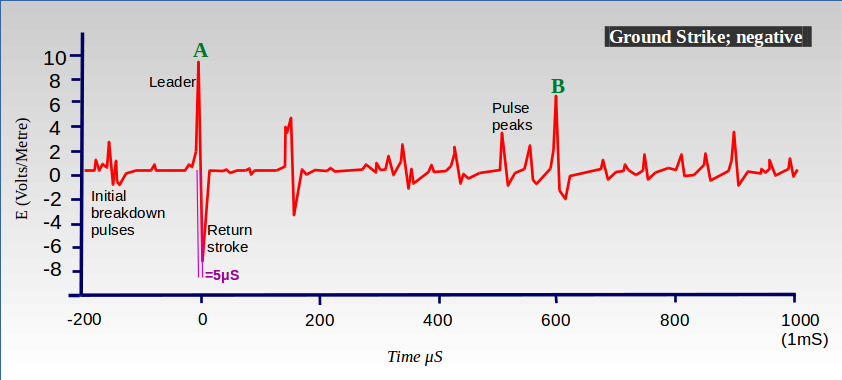
If the lightning is a Ground-strike, it will probably weld the contacts together... ... and if it's an Air-strike, the contacts will probably be sufficiently open just as the main lightning pulses arrive, thereby preventing the SPD from seeing them!
Lightning is a series of around 20-pulses, of which the ones with most energy will be numbers 10 to 14.
Sleep well.
I hear thunder's on the way.
This post was modified 3 months ago by Transparent
I've labelled three pairs of double-insulated tails.
Pair-A go from the central Switch Disconnector to something... possibly the main house Consumer Unit.
Pair-B return from that something and go to the pretty Henly Blocks on the right.
The Zappi EV Charger is supplied from the top of those Henly Blocks.
Pair-C go to something else, which I assume is the Black DIN Enclosure you're calling a Tesla Gateway.
Please confirm if I've correctly identified those three Pairs.
The Tesla Gateway sits between the incoming supply and the CU, so I would postulate that Pair A go to the Gateway with Pair B returning from the Gateway to Henley blocks, and Pair C then go to the consumer unit. The Gateway allows the house to be physically disconnected from the Grid (Pair A) by opening a relay for full home backup.
The solar connects directly to the Powerwall battery (with inbuilt inverter and DC isolation). The battery AC output connects to the Gateway allowing solar/battery to supply either to house loads (via Pair B then Pair C to the CU) or back to the grid as export via Pair A. Similarly, the battery (PW3) can charge from directly connected DC coupled solar or import from the grid via Pair A to the Gateway and from there direct connection to the Powerwall.
I'm now a little out of my depth, so I asked AI for input:
Does the Tesla Gateway require an RCBO or RCD to be fitted?
The Tesla Backup Gateway itself does not strictly require an internal or dedicated RCD or RCBO for the Powerwall's automatic disconnection, as the Powerwall safely drops voltage in an off-grid fault. However, depending on local wiring regulations (e.g., in the UK or Ireland), you may need RCD/RCBO protection for site-level cabling, TT earthing networks, or downstream home loads.
When mandated, 300 mA Type AC or Type A RCDs/RCBOs are typically recommended to prevent nuisance tripping. A Type B RCD is usually not required for the Powerwall itself.
Note the part about nuisance tripping. That missing RCD is recommended to prevent nuisance tripping. I would ask the installer to install the missing RCD in the Gateway.
I'm not an expert on UK wiring regulations, but is the missing RCD required to protect the downstream wiring (Pair B > Pair C > CU)? Or perhaps it is there to protect the AC connection between PW3 and Gateway?
Also, moot point, but the Powerwall commissioning process requires the off grid functionality to be tested during commissioning where a Gateway is installed so the installation was not properly commissioned. I would get the installers back to fix. If you google the phrase AI has returned above, you will probably find the Tesla installation manual it has pulled it from, which you can show your installer.
EDIT: This is the RCD I have installed in my Gateway.
EDIT 2: I'm pretty sure my RCD is as per Option one here. This is the Tesla documentation I would show to your installer.
This post was modified 3 months ago 9 times by Old_Scientist
Samsung 12kW gen6 ASHP with 50L volumiser and large radiators. 7.2kWp solar (south facing), Tesla PW3 (13.5kW). Net Zero
@transparentsparentent @old_scientist thank you both for comprehensive inputs.
Yes, I believe @old_scientist has the correct routing and makes sense with the Gateway installed just to that side of the meter box
The grey Wagobox is related to the Zappi and black CT Clamp
Earth rod from Gateway is installed directly beneath the Gateway
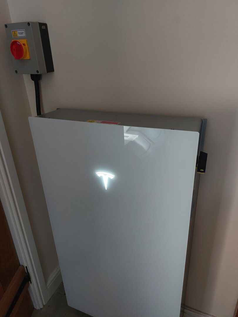
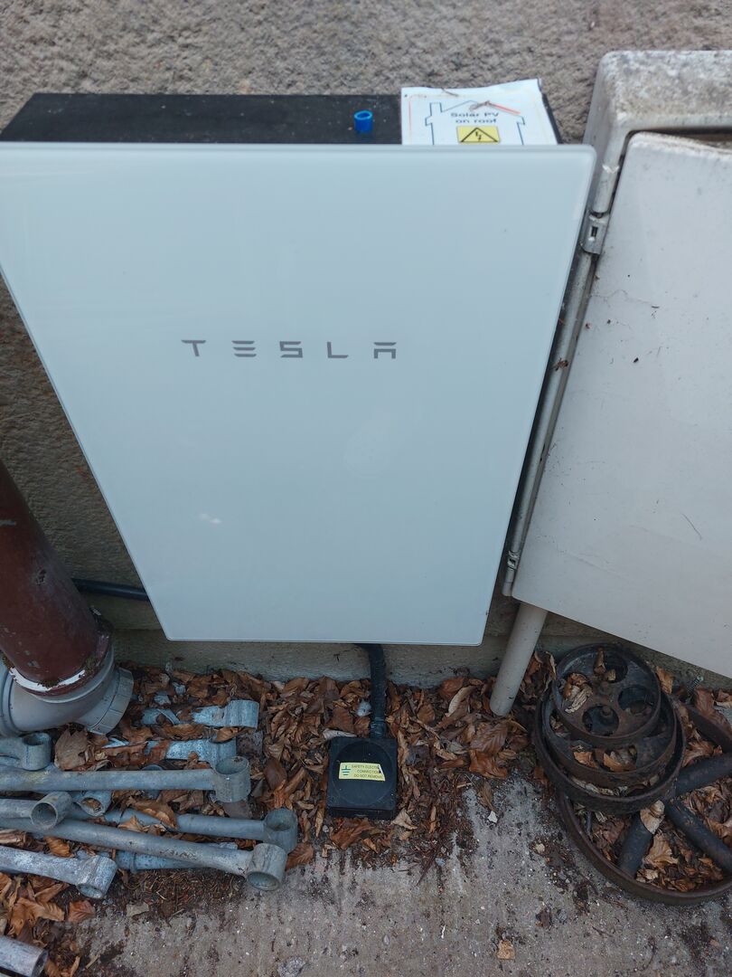
It is a Powerwall3. The DC isolator is on the right of the Powerwall (combined inverter and battery). AC isolator is the box separate from Powerwall at top left
Listed Grade 2 building with large modern extension. LG Therma V 16kw ASHP Underfloor heating + Rads 8.7kw pv solar 3 x 8.2kw GivEnergy batteries 1 x GivEnergy Gen1 hybrid 5.0kw inverter Manual changeover EPS MG4 EV
I agree a big mistake was made in not testing the off grid function during commissioning. I have not completely lost faith in the installer but am obviously concerned. They are not local which does not help with problem resolution.
I agree we may be lacking earthing of the panels - maybe more so as they're on a metal roof. It's something I'm trying to get confirmed on requirements as I have a similar setup at my house with GivEnergy inverter- pv solar on metal roof but lacking earthing. That installation goes back to 2021 but assume regs have not significantly changed.
The Zappi was installed 3 years ago by Octopus- I would hope they had got it right. I'm not sure what to do at this point. Possibly a regular electrician can check & test sufficiently?
This post was modified 3 months ago 2 times by Tim441
Listed Grade 2 building with large modern extension. LG Therma V 16kw ASHP Underfloor heating + Rads 8.7kw pv solar 3 x 8.2kw GivEnergy batteries 1 x GivEnergy Gen1 hybrid 5.0kw inverter Manual changeover EPS MG4 EV