

Notifications
Clear all
Joining the Renewable Heating Hub forums is completely free and only takes a minute. By registering you’ll be able to ask questions, join discussions, follow topics you’re interested in, bookmark useful threads and receive notifications when someone replies. Non-registered members also do not have access to our AI features. When choosing your username, please note that it cannot be changed later, so we recommend avoiding brand or product names. Before registering, please take a moment to read the Forum Rules & Terms of Use so we can keep the community helpful, respectful and informative for everyone. Thanks for joining!

18/07/2026 12:21 pm
A resistor won’t clear up noise.
Is that the case? Surely the terminating resistor also reduces the impedance of the circuit, and thus induced currents will generate smaller voltages
You may well be right; I am by no means an expert. It’s my understanding, but I am happy to be proven wrong. I’d welcome any electronics experts to wade in at this point.
105 m2 bungalow in South East England
Mitsubishi Ecodan 8.5 kW air source heat pump
18 x 360W solar panels
1 x 6 kW GroWatt battery and SPH5000 inverter
1 x Myenergi Zappi
1 x VW ID3
Raised beds for home-grown veg and chickens for eggs
"Semper in excretia; sumus solum profundum variat"

18/07/2026 2:20 pm
If it is RS485 (is it?)...
It uses balanced/differential twisted pair link. The idea is to send the signal on one wire, and the inverted signal on the other wire. For example, one wire +5V the other 0V to send "1", and one wire 0V the other +5V to send "0".
Voltage between both wires is called "differential mode" and is your actual signal. Voltage between the average of both wires and receiver ground is called "common mode". In the above example, differential mode is either +5V for "1" or -5V for "0" and common mode is 2.5V.
The idea behind balanced differential transmission is:
1) The receiver compares (or subtracts) voltages on both wires to decode what was transmitted. It does so while doing its best to ignore common mode: shifting both wires' voltage by the same amount doesn't change the result.
2) We want both wires to receive noise in the exact same way, ie common mode, so the receiver can reject it. For this, the wires should have the same impedance, and they should be twisted.
Two parallel wires in a perpendicular electric field receive a noise voltage between them. Twisting the wires cancels that, and also makes more of the noise common mode.
In a variable magnetic field, induced current in a wire loop is proportional to loop area. Area between the wires is tiny, so for all intents and purposes, there is almost no induced current in the loop formed by the two wires. However, the cable is long, and it forms a very large loop with the other return wire, which is Protection Earth. Therefore, induced current problems are mostly common mode, within the loop Device1 - comms cable - Device2 - Earth - Device1. The solution to this is to use isolated RS485 transmitters to break the loop (this is very common), and connect the cable shield at both ends to ensure both RS485 chips have a common ground and don't see harmful common mode voltages. Ironically this is almost never done, all you get is two terminals "A" and "B" and nothing to connect the shield, which makes the shield mostly useless.
The termination resistor is to avoid signal reflections in the transmission line, which only cause problems if the rise time of the signal is quicker than propagation time in the transmission line. This is not usually an issue at the low baud rates used in these links.

18/07/2026 4:37 pm
Samsung 12kW gen6 ASHP with 50L volumiser and large radiators. 7.2kWp solar (south facing), Tesla PW3 (13.5kW). Net Zero


24/07/2026 12:22 pm
@Steveimpey, having skimmed through the manuals and the replies above, my non-expert reading is that there are two separate issues here.
Firstly, the installation does not appear to follow Samsung’s instructions. The Gen 6 guide specifies a 0.75mm2, two-core screened cable for the F1/F2 communication link. If ordinary CAT6 was used instead, then the installer or electrician seems to have departed from a fairly clear manufacturer requirement. As the homeowner, you could not reasonably have been expected to know that, and I don’t think you should simply be left with the cost of correcting it. That is not your error.
Where I’m much less convinced is Samsung’s explanation that interference made the communication chip "work harder" until it failed. I’m not an electronics or data-cabling expert, but I’m very much with @jamespa and @bobflux on this. The manual identifies E101 as a communication fault and directs the engineer to check the cable and the voltage at the communication terminals. That does not, by itself, prove that the cable damaged the PCB.
As I understand it, CAT6 is designed to carry data and uses twisted pairs to help reject interference. That does not mean it was the correct cable for this installation, because Samsung specified something else, but it does make the "microscopic amounts of data" explanation sound rather questionable and frankly dubious.
The more plausible concerns raised above seem to be whether the CAT6 was screened, how it was routed, whether it ran close to mains cables, how long the run was and whether the smaller conductors were properly secured in Samsung’s terminals. @bobflux’s point about thinner solid conductors being less mechanically robust also sounds considerably more credible to me than the idea that the chip has been physically straining itself for three years.
I also wouldn’t start adding termination resistors or altering the communication circuit unless Samsung’s own documentation specifically calls for it. That feels like something that should be established by the manufacturer or a properly qualified engineer, rather than improvised while trying to diagnose the fault.
Before agreeing to pay for a replacement PCB, I would ask for the diagnosis in writing. They should confirm the exact cable fitted, what tests were carried out, what voltage was measured at the communication terminals and how they have established that the board itself has failed rather than there simply being a cable, connection or routing problem.
It would also be sensible to retain the removed cable, or at least photograph the markings printed along it before it disappears. That may help establish exactly what was installed.
My layman’s view is that the incorrect cable should be replaced because it does not match Samsung’s specification. But that is not the same as proving that it destroyed the PCB. Samsung and the installer need to provide evidence for that second claim rather than expecting you to accept it.
And from your perspective, this was one heat pump installation. You should not be left trying to arbitrate between the installer, electrician and manufacturer while each points at someone else.
The cable specification seems fairly clear, but the claimed cause of the PCB failure certainly does not.
🔥 Britain’s Heat Pump Shitshow
How Installing a Heating System Became a National Nervous Breakdown
Free UK shipping.
📗 Heat Pumps Explained
A Jargon-Free Guide for Homeowners
Rewritten and updated for 2027
📘 From Zero to Heat Pump Hero
🛠️ Bodge Buster
New to heat pumps?
Take the Heat Pump Fundamentals course and use INTRO50 at checkout for 50% off.
1

24/07/2026 6:17 pm
+1
CAT5 and 6 work absolutely fine for RS485 until the wires break, which will happen eventually if vibration is present or someone opens the panel and moves the wires enough times to access something hidden behind or work on unrelated wiring. When not terminated with suitable jacks (RJ) or connectors that hold the cable itself with strain relief, these are very fragile. Not suitable for use with screw terminals, inside a consumer unit or electrical panel, simply due to lack mechanical robustness.
CAT5 and 6 cannot "make the electronics work harder and then burn" whatever that means.
Most RS485 chips will survive a shorted RS485 connection (short between A, B, +5V or GND) but will get quite hot which will shorten their life. Whatever the extra current drawn by the short does to the board's power supply depends on the design. If it burns out, then it was bad design. Most modern chips will self protect. Some cheap ones won't.
No RS485 chip will survive shorting the RS485 wire(s) to high voltage, mains, etc. This would propagate through the whole board and destroy it, most likely result being a completely dead board. If the RS485 interface is galvanically isolated, then shorting ONE wire to mains should not destroy anything, but applying mains between both A/B wires will destroy everything on the side of the isolation barrier that gets zapped, while the rest of the board should survive.
With a multimeter, if you stick the probes in RS485 A/B with no wires connected you should get +/-5V or +/-3.3V depending on polarity. If it is transmitting, then voltage will vary periodically and this indicates the device works. If it is idle, voltage will be fixed so this doesn't tell whether it works or not.
24/07/2026 10:28 pm
I serviced my Samsung 12kW gen6 heat pump today, so whilst I had the case off I took the opportunity to check the F1 / F2 wiring and snap a couple of photos.
As can be seen in the images, the cable looks much like a cat5/6 network cable, but it is actually 2 x 0.75mm2 cores with screening or drain wire which is earthed on the chassis of the outside unit. The cabling is terminated with spades or lugs with screw down terminals.
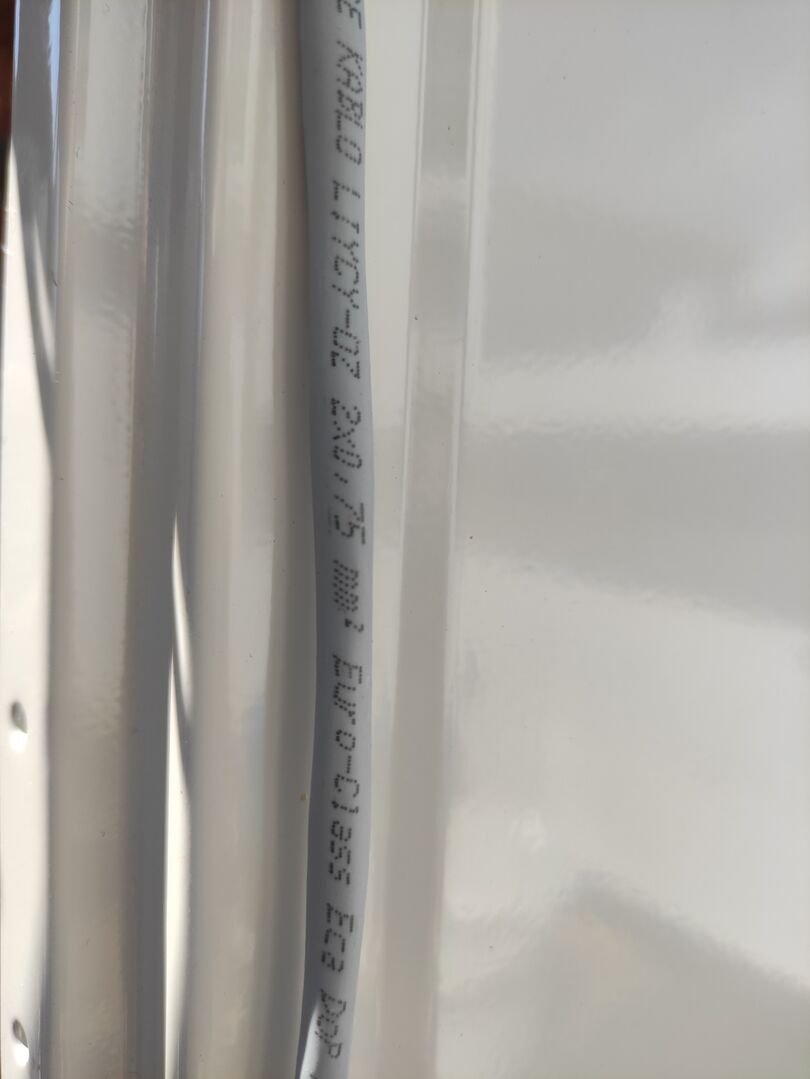
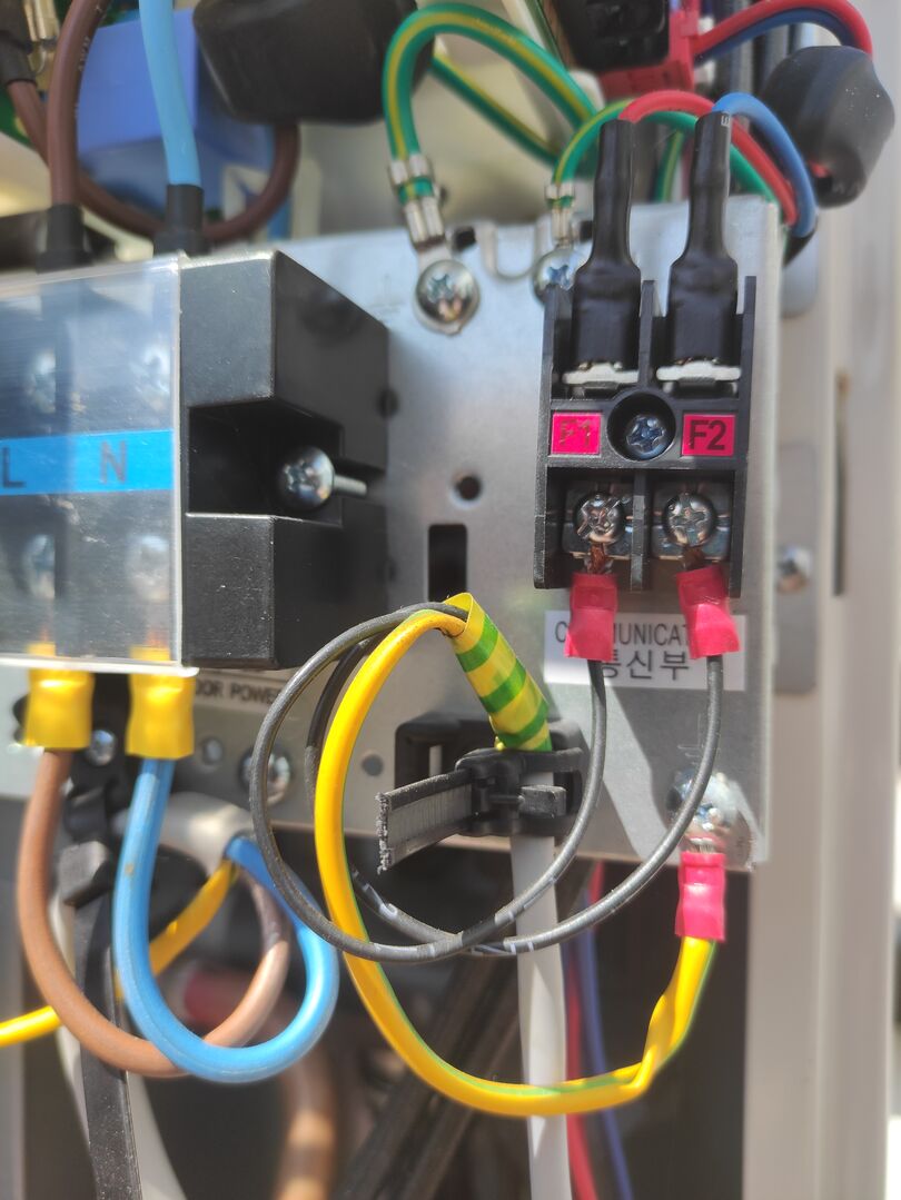
This post was modified 3 months ago by Old_Scientist
Samsung 12kW gen6 ASHP with 50L volumiser and large radiators. 7.2kWp solar (south facing), Tesla PW3 (13.5kW). Net Zero
25/07/2026 5:37 am
That's well done. Cable is the correct type (LIYCY = 2x stranded copper wires + copper braid shield). The zip tie holds the cable itself, there is no strain on the wires, shield is connected to chassis ground, and they used crimp lugs.
2
Page 2 / 2
Prev
SPONSORS

Degrees of Separation
Latest Posts
-

RE: New Build 3 Phase or 1Phase
@etchedpixels I've just looked back, it was March this ...
By E A WEST , 1 hour ago
-
RE: How will removing the standing charge on gas bills benefit heat pumps?
I'm not sure it makes much of a difference to heat-pump...
By Temperature_Gradient , 15 hours ago
-
@editor Ouch, sorry to re start the tick. I had assume...
By DavidB , 16 hours ago
-
RE: Say hello and introduce yourself
@e-a-west as the good Major said, welcome to the forums...
By Mars , 17 hours ago
-
RE: How much of your renewable and home setup would still work if the internet went down?
Yes I actually have a copy of a tool that whenever a ce...
By EtchedPixels , 1 day ago
-
RE: Indevolt Batteries UK Support & Info Thread
@editor Hi, To resolve this, please tap on the A...
By Indevolt Tech , 1 day ago
-
RE: Double or Triple Glazed Windows?
Posted by: @singlespeed With 9 years repairing windo...
By Rob of York , 2 days ago
-
@transparent we’re still running a secure version of PH...
By Mars , 2 days ago
-
RE: How quickly would you want/expect heat recovery to take from setback?
Much longer than that here. The heating isn't even on. ...
By bobflux , 3 days ago
-
RE: Passiv Smart Thermostat - Help & Forum Support
Obviously the weather is changeable but there's a defin...
By Singlespeed , 3 days ago
-
RE: The Changing Jet Stream Could Challenge UK Air Source Heat Pumps
@rob-of-york I must admit that when we had a Daikin hea...
By Toodles , 3 days ago
-
RE: Forum updates, announcements & issues
Get the Renewable Heating Hub heads-up on WhatsApp. I...
By Mars , 3 days ago
-
RE: Safety study for plug in batteries out to tender - looks like Q3 2027 at best before legal
@editor I pointed out to the one of the Fuse execs that...
By dansus , 3 days ago
-
RE: 15kw pump for 225m2 1990's house - over kill?
@seaviews As well as loft insulation, there are othe...
By Rob of York , 3 days ago




SPONSORS