Notifications
Clear all
Joining the Renewable Heating Hub forums is completely free and only takes a minute. By registering you’ll be able to ask questions, join discussions, follow topics you’re interested in, bookmark useful threads and receive notifications when someone replies. Non-registered members also do not have access to our AI features. When choosing your username, please note that it cannot be changed later, so we recommend avoiding brand or product names. Before registering, please take a moment to read the Forum Rules & Terms of Use so we can keep the community helpful, respectful and informative for everyone. Thanks for joining!

Topic starter
10/11/2026 5:51 pm
We have a setup where there are 2 x 14kW Ecodan units (PUZ-HWM140VHA) recently fitted in a 6 bed bungalow that has an indoor pool. There are a couple of radiator circuits, and three UFH circuits, and a circuit for the pool heating. At the moment, the system is consuming over 60kWh of electric a day, and it has not really got that cold down here in Suffolk yet...
What seems questionable is the buffer tank set up: There is a 45lt Vaillant tank (VP RW 45/2 B), which if needed at all, seems quite small, or piped up wrong.
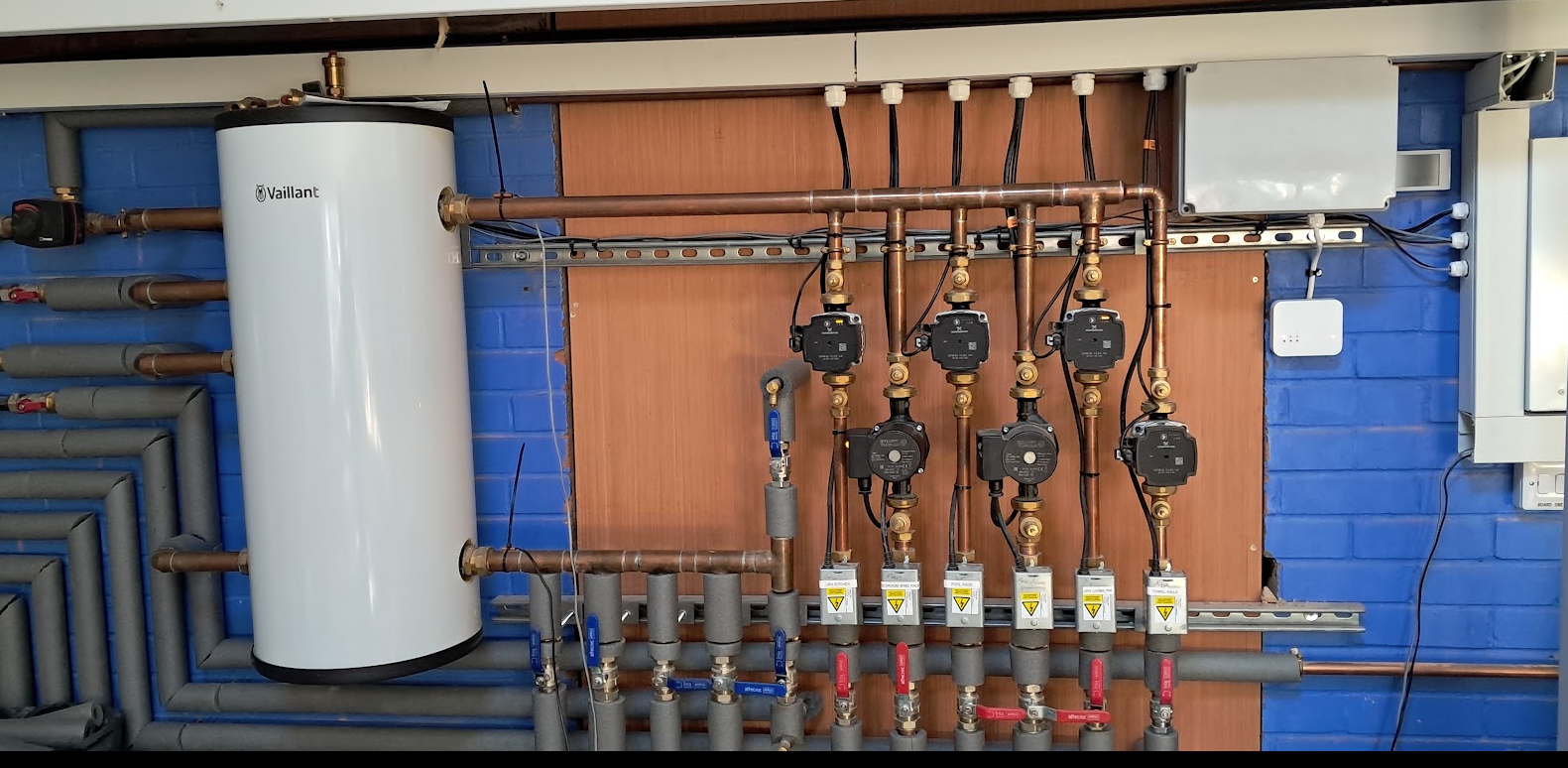
The image above shows the set up - on the LHS of the tank, the pipes, starting at the top, are 1) ASHP1 flow, 2) ASHP1 return, 3) ASHP2 flow & 4) ASHP2 return. The top 3 pipes are 120mm apart. On the RHS, top pipe is flow to the emitters, bottom one is return. Just out of shot on the left, there are the circulation pumps that are on the return sides, so effectively "sucking" the return to each ASHP (correctly), so the draw for the system is the pumps on each of the circuits on the RHS.
It does not make sense to me that for ASHP1, no sooner is the hot water sucked into the buffer tank, the return pipe immediately below is sucking it out again, and if ASHP2 joins in, its flow in is immediately below the return of ASHP1, which again is going to be sucked out by ASHP1 before getting across the tank to the emitter side. The flow temp from both ASHPs is set to 40c (to achieve a pool temp of 29c), and the flow pipe on the emitter side of the tank measures 37c, so a loss of 3c before anything starts circulating.
Looking at the manufacturers info on the tank, it shows it is used for a combined gas boiler / single ASHP set up, with the top two pipes being for a gas boiler flow and return, and the pipe 3 is ASHP flow, and pipe 4 at the bottom is for ASHP return (which makes sense).
What I am looking for is advice on whether that buffer tank is completely wrong for my 2 x ASHP set up, and if so, what would be correct? No buffer tank at all? A separate buffer tank for each ASHP (if so, is 45lt appropriate?) or perhaps a 100lt buffer, with the flow in the top two pipes, and the returns at the bottom, or volumisers rather than a buffer set up, or possibly a completely different solution!
Thanks in anticipation... 😀

SPONSORS

Degrees of Separation
Latest Posts
-

RE: Should Households Who Can Afford It Pay More for Energy to Help Those Who Can't?
I think we also have to be careful when bailing out peo...
By Batpred , 3 minutes ago
-
Buffer tank on a 2 x 14kw Ecodan system
We have a setup where there are 2 x 14kW Ecodan units (...
By fosterl2 , 1 hour ago
-
RE: Why don't people choose heat pumps?
@rob-of-york The Panasonic units also have a microscopi...
By Toodles , 2 hours ago
-
RE: Adventures in heat loss calculations
@toodles thanks! So as suspected, around a doubling of ...
By SusannaSaunders , 2 hours ago
-
Six books in three years and I think I’ve now covered j...
By Mars , 3 hours ago
-
RE: Grant Aerona3 13kw - Buffer Tank - Heating Journey
@heymikey Well done in achieving as nearer a match acro...
By Toodles , 9 hours ago
-
RE: DIY powerflushing tutorial
I didn't throw it away. Is there a way to determine wha...
By bobflux , 10 hours ago
-
Grant Aerona - Weather Compensation and Schedules
Im trying to set up a friends Grant Aerona. The WC curv...
By bontwoody , 1 day ago
-
RE: Air-to-Air Heat Pumps & Air Conditioning: UK Heating and Cooling Q&A
@jamespa I agree, the efficiency of Cosy Cooler ought...
By Rob of York , 1 day ago
-
RE: How much of your renewable and home setup would still work if the internet went down?
I think you're right! 🤨
By Transparent , 2 days ago
-
RE: Renewables & Heat Pumps in the News
ECO4 muddies the water somewhat, and then some. I thi...
By cathodeRay , 2 days ago
-
RE: Vaillant ecoTEC Plus - Flow Temp and Set Up
If there is a drain nearby that's exactly what I would ...
By JamesPa , 2 days ago
-
I think that CCGT plant in Lingen is more likely to suc...
By Transparent , 3 days ago
-
RE: Heat Geek installations: share your experiences
@l8again fwiw my experience (Valiant but not with heat ...
By JamesPa , 3 days ago
-
RE: How Can I Prove Coal Was My Main Heating Source Without Receipts?
@etchedpixels thank you for the advice paid cash all...
By Chilli304 , 4 days ago


SPONSORS