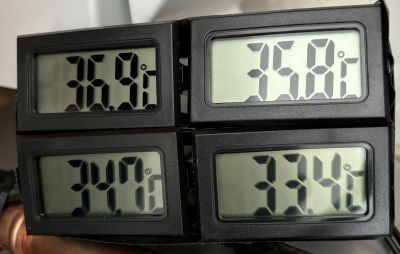
I purchased some LR44 button Cells and powered up the 4 sensors; I laid the four probes close together and placed a Govee thermometer on either side of this bundle of sensors. The Govees both indicated the same temperature and I left the whole caboodle for 5 days occasionally comparing the readings on all four sensors to the Govees. I found that two of the sensors were consistently 0.1 degree C low and 0.1 degree C high and the others were 0.9 and 1.1 degrees C lower than the Govees. The four displays were then taped into a little ‘block’ and the probes taped onto the LLH pipes and covered with insulation. I left the probes to settle for an hour and then read (as per the photo) the results. Top left and bottom left are the heat pump flow and return; the top right and bottom right are the flow from LLH to emitters and return respectively. The left hand displays are both within 0.1 degree of Govee reference and the right hand pair are 0.9 and 1.1 degrees of reference. Outside temperature (according to Daikin Onecta app) was 13 degrees C and heat pump and secondary pump are noth working. Any comments welcomed but I’ll see what results show when OAT becomes more winter-like. (One other thing, supplier has not supplied replacement button cells so have reported them to Amazon) Regards,, Toodles.
Toodles, heats his home with cold draughts and cooks food with magnets.
So applying the correction factors which you have established, the LWT is 37C and the RWT is 34.8C, giving a DT of 2.2C in the primary circuit. On the secondary side of the LLH the flow temperature is 36.7C and the return temperature is 34.5C, again indicating a DT of 2.2C.
The temperature drop across the LLH is only 0.3C, so I would assess that your system is operating in quite an efficient manner.
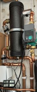
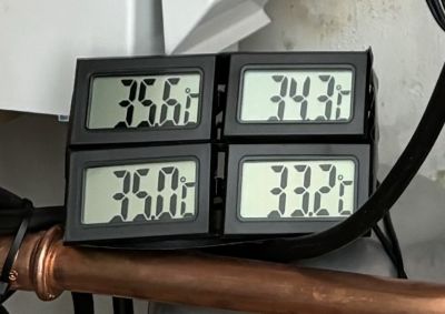
@derek-m Hello Derek, I have left the system running with the thermometers in place for a few weeks now; glancing at the readings from time to time indicates that the varying OAT’s for a constant IAT show that the differential is fairly consistent. The displays are: Top Left = Flow to LLH. Top right = LLH flow out to rads, Bottom right = Return from Rads and Bottom Left = Return from LLH to ASHP. With the correction factors of the two right hand displays being 1 degree C. lower when all sensors were bunched together for several days, I am applying a +1 degree to these two thermometer readings; though I know these are not super-accurate devices, I think they probably provide a reasonable indication of the trends of changing temperature at the 4 points. I seem to have an average drop of 0.2 - 0.3 degrees across the input from the flow to the output of the LLH and 0.3 - 0.6 degrees C. across the return to the LLH and the return to the ASHP.
From time to time, I notice a dynamic ‘blip’ from time to time where one display or the other might indicate perhaps a 1 degree difference but this is short lived usually. I even noticed a difference of 4 degrees momentarily where the flow into the LLH exceeded the reading on the flow out to the rads; this lasted about 30 seconds or so and I have no idea why this should happen.
I don’t know the make of LLH as no label is visible but it is approx. 46 cm. Tall and 17 cm. wide.
Observations welcomed please!. Regards, Toodles.
Toodles, heats his home with cold draughts and cooks food with magnets.
I suspect that the image was subjected to some filesize reduction so here is a close up of the displays. Toodles.
Toodles, heats his home with cold draughts and cooks food with magnets.
I believe that the temperature readings indicate that your system is quite well balanced, in that the flowrate into the LLH is slightly greater than the flowrate out to the radiators.
This is probably the optimum achievable situation, since the slight mixing that is taking place within the LLH is at the return flow end. Slight mixing of the return flow should not have a detrimental effect on heat pump operation and overall efficiency.
Thank you Derek, at least it is only a little ‘Devil’ then! Regards, Toodles.
Toodles, heats his home with cold draughts and cooks food with magnets.
Many of you may be aware of my growing skepticism towards certain elements of the heat pump, and one aspect I find particularly perplexing is the position held by both manufacturers and installers of heat pumps. This confusion was further compounded following my participation in an online discussion involving a group of installers and a representative from one of the leading heat pump manufacturers. The debate quickly escalated, especially around the topic of buffer tanks, reaching a point of intense contention. Interestingly, the manufacturer chose to remain notably silent as the installers, who were divided in their opinions, engaged in a heated exchange.
The crux of the debate revolved around whether buffer tanks could be installed efficiently and effectively by installers in general. The conversation revealed that integrating a buffer tank with a low temperature heat pump system, along with managing all related components, is a complex process. It became evident that a significant number of installers in the UK lack the necessary skills and training to execute such an installation successfully. Prompted by this realisation, I questioned why the industry doesn't move away from using buffer tanks altogether to avoid the complications associated with their installation.
This query led to an unexpected direct message from a high-ranking official within the manufacturing company, asserting their unequivocal support for the use of buffer tanks and their desire for these components to be incorporated into installations, regardless of the efficiency of the installation process. Needless to say, this was a private exchange, and a position they didn’t want to express publicly.
This admission was startling and left me perplexed about the overarching objectives of the heat pump industry. It begs the question: why are we installing advanced heat pump systems only to undermine their performance with suboptimal installations? Surely, the ultimate aim should be to ensure that we are installing the most efficient systems possible, rather than settling for setups that significantly impede their functionality.
Get a copy of The Ultimate Guide to Heat Pumps
Subscribe and follow our YouTube channel!
@editor Mars, as you might know, we have an LLH (which fortunately seems to be running with relatively low losses to the efficiency 😉). I am not about to rip out the LLH to extract a little more efficiency though! The majority of installers seem to opt for an LLH or a Buffer Tank by default as a ‘rear covering’ exercise don’t they? I had a long conversation with the director of the installers and he seemed to view the situation as a positive addition as it removed the necessity to achieve such a delicate setting of the Delta T performance from the secondary circuit that fed the emitters. I think our system is running well, but there is always the nagging feeling …’Might my Air Source Heat Pump run more efficiently if I had the LLH removed?’ Regards, Toodles.
Toodles, heats his home with cold draughts and cooks food with magnets.
The cynic in me says this is about reducing call-outs & guaranteeing adequate volume for defrost. From a customer POV, as well as having the potential to be poorly installed, a buffer increases cost and takes up space which many may not have.
It would be worth, IMHO, pressing them on the question of whether they mean 'buffer tank' or 'volumiser'. The latter at least has less potential for poor installation.
4kW peak of solar PV since 2011; EV and a 1930s house which has been partially renovated to improve its efficiency. 7kW Vaillant heat pump.
Is there also a danger in the terminology that is being used ie low loss header, buffer and volumiser. Not all LLH's act as buffers, correctly specified and installed they operate perfectly correctly as a hydraulic separator. It very much depends on where on the LLH the ports are positioned.
Are we in danger of vilifying an entire class of products?
Posted by: @abernyteIs there also a danger in the terminology that is being used ie low loss header, buffer and volumiser. Not all LLH's act as buffers, correctly specified and installed they operate perfectly correctly as a hydraulic separator. It very much depends on where on the LLH the ports are positioned.
Are we in danger of vilifying an entire class of products?
As far as I am aware there would be no problem with a LLH or buffer tank, if the primary and secondary flowrates can be balanced to ensure that no mixing of the flow and return takes place. Obviously balancing the flowrates becomes problematic if the heat pump controller is able to vary the primary flowrate, without the necessary adjustment also being performed on the secondary, thereby unbalancing the system.
Having an additional water pump that may not be necessary is also a possible waste of electrical energy.
-
British Gas Heat Pump Installation Complaint
4 months ago
-
Heating Turned Off but Radiators Still Warm
4 months ago
-
Samsung Heat pump with Yonos Pico circulating pump running all the time
4 months ago
-
Samsung 5kW R32 Monobloc Gen 6 ASHP
5 months ago
-
Ideal Logic 10kW Heat Pump Pipes Noisy and Very Expensive to Run
1 year ago
Currently viewing this topic 1 guest.
- 27 Forums
- 2,495 Topics
- 57.8 K Posts
- 343 Online
- 6,220 Members
Join Us!
Worth Watching
Latest Posts
-
RE: What determines the SOC of a battery?
@batpred I didn't write the Seplos BMS software, I a...
By Bash , 12 minutes ago
-

RE: Electricity price predictions
Sorry to derail this thread ‘slightly?’ but back to the...
By Toodles , 21 minutes ago
-

RE: Humidity, or lack thereof... is my heat pump making rooms drier?
Without knowing it, @andrewj, you've laid down the gaun...
By Majordennisbloodnok , 41 minutes ago
-
RE: Testing new controls/monitoring for Midea Clone ASHP
@tasos and @cathoderay thanks. I have some history grap...
By benson , 45 minutes ago
-

I am having my existing heat pump changed to a Vaillant...
By trebor12345 , 1 hour ago
-
Our Experience installing a heat pump into a Grade 2 Listed stone house
First want to thank everybody who has contributed to th...
By Travellingwave , 2 hours ago
-
RE: Setback savings - fact or fiction?
@cathoderay The input power is largely determined by...
By RobS , 2 hours ago
-

RE: Solis inverters S6-EH1P: pros and cons and battery options
Just to wrap this up here for future readers: The S...
By Batpred , 4 hours ago
-
RE: Struggling to get CoP above 3 with 6 kw Ecodan ASHP
Welcome to the forums.I assume that you're getting the ...
By Sheriff Fatman , 4 hours ago
-
RE: Say hello and introduce yourself
@editor @kev1964-irl This discussion might be best had ...
By GC61 , 6 hours ago
-

@painter26 — as @jamespa says, it's for filling and re-...
By cathodeRay , 10 hours ago
-

RE: Oversized 10.5kW Grant Aerona Heat Pump on Microbore Pipes and Undersized Rads
@uknick TBH if I were taking the floor up ...
By JamesPa , 20 hours ago
-

RE: Getting ready for export with a BESS
I would have not got it if it was that tight
By Batpred , 22 hours ago
-
RE: Need help maximising COP of 3.5kW Valiant Aerotherm heat pump
@judith thanks Judith. Confirmation appreciated. The ...
By DavidB , 1 day ago
-

RE: Recommended home battery inverters + regulatory matters - help requested
That makes sense. I thought better to comment in this t...
By Batpred , 1 day ago
-
Bosch CS5800i 7kW replacing Greenstar Junior 28i
My heat pump journey began a couple of years ago when I...
By Slartibartfast , 1 day ago
-

RE: How to control DHW with Honeywell EvoHome on Trianco ActiveAir 5 kW ASHP
The last photo is defrost for sure (or cooling, but pre...
By JamesPa , 1 day ago
-

RE: Plug and play solar. Thoughts?
Essentially, this just needed legislation. In Germany t...
By Batpred , 1 day ago
-
RE: A Smarter Smart Controller from Homely?
@toodles Intentional opening of any warranty “can of wo...
By Papahuhu , 1 day ago
-
RE: Safety update; RCBOs supplying inverters or storage batteries
Thanks @transparent Thankyou for your advic...
By Bash , 1 day ago
-
RE: Air source heat pump roll call – what heat pump brand and model do you have?
Forum Handle: Odd_LionManufacturer: SamsungModel: Samsu...
By Odd_Lion , 1 day ago
-
RE: Configuring third party dongle for Ecodan local control
Well, it was mentioned before in the early pos...
By F1p , 2 days ago
-

RE: DIY solar upgrade - Considering adding more panels
I know this is a bit old, but it made me wonder what co...
By Batpred , 2 days ago


