Buffers, hot water and cooling
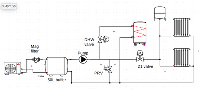
I have a 13kW Grant ASHP, installed to the letter of Grant's instructions at the time. 50 litre buffer, 200 litre DHW cylinder, radiators (with TRVs which are never used), wired as classic S-plan. After I rewired it to use the native ASHP controls since the installer followed the (very mistaken) Grant instructions, it works well for heating and hot water. The ASHP is maybe a bit oversized (deliberately, for noise reasons) but it seems to work fine - no short cycling. On mild days it'll run for a short time to heat the buffer and then circulate that heat for an hour or few around the house (ie the buffer is doing its job). It's set to run 'sniff' cycles every 20 minutes, ie run the internal pump to take the temperature of the buffer water by sending it past the outdoor unit's temperature probe and decide whether to turn on or not*. Here's a diagram:
(* I have actually wired a buffer thermistor so it can measure the buffer temperature directly, but it seems the only mode it'll use that is when it tries to keep the buffer at a constant temperature like a gas boiler - no weather compensation or anything, which isn't what I want. When I disable that mode the buffer temperature always reads 25C - seems using sniff cycles is the only option in more sensible modes.)
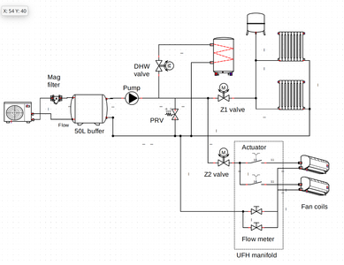
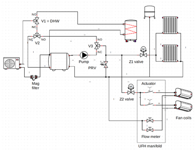
I'm pondering installing some fan coils for cooling. Current thinking is to install them on a second zone (S-plan+) like an upside down underfloor heating system: UFH manifold, UFH actuators, and no valvegear in the fan coils (easier to manage condensation that way). Sketch:
Are there any reasons not to go with this plan? I've tested the ASHP by switching the cables to the DHW and Z1 zones and running it in cooling mode - it makes a nice tank of chilled water (although the coldest water sinks to the bottom of the tank and the draw is at the top, so you can't actually chill the whole tank to 7C even if that's what it's making).
One thing I wondered was about the buffer when switching between DHW and cooling. If you've just made a tank of hot water for a shower then want to switch to cooling mode. What happens when you engage cooling is the unit runs its internal pump and the fan with no compressor to cool down the buffer circuit to outside temperature, and then runs the compressor to cool it below ambient. But this is inefficient as every time you switch from hot water to cooling you have to cool that 50+ litres, and heat it again when you want hot water. Typically I have it set to just run the hot water any time the water temperature gets a bit low, which can be at any point in the day. Let's assume that I just want a fit and forget option, ie I don't want to micromanage scheduling the hot water at 3am to avoid conflicts with cooling. It seems less than ideal to have hot water and cooling fighting like this.
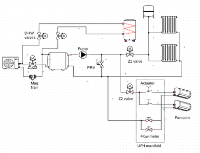
One option would be to move the DHW before the buffer, on the basis that there will always be a constant flow through the DHW circuit. This would then move the buffer into the heating/cooling side only, and allow a switch between heating and cooling modes without having to shift the buffer water. Something like:
What would be the pros and cons of this approach? I need to do the calculation of the ASHP's minimum flow against flow through the hot water cylinder coil, but let's assume that's ok. I'd have thought there would be enough heat in the DHW side to scavenge for defrost cycles when in DHW mode, and in heating mode there's still the buffer. If one of the valves stuck presumably the ASHP would shut off to protect itself for lack of flow. Any other things to watch out for, or reasons why this isn't a good idea?
Edit: maybe I'll need to move the expansion tank to before the Z1 and Z2 valves, to manage pressure when in cooling mode too?
Posted by: @prunusOne option would be to move the DHW before the buffer, on the basis that there will always be a constant flow through the DHW circuit.
This is how my system is arranged, with a three port valve that switches the HP flow either directly to the DHW or to the buffer when in heating /cooling mode.
Mitsubishi Zubadan 14kW with Mixergy 210l DHW in 220m2 barn property. 24 solar panels = 9kWp with GivEnergy 5.0kW Hybrid inverter and 19kWh GivE batteries. Jaga Strada fan-assisted rads throughout. Landvac vacuum glazing/triple glazed windows.
Posted by: @prunusOne option would be to move the DHW before the buffer, on the basis that there will always be a constant flow through the DHW circuit. This would then move the buffer into the heating/cooling side only, and allow a switch between heating and cooling modes without having to shift the buffer water
Definitely do this. My dhw operates fine without a buffer or volumiser and your logic explains why.
Posted by: @prunusEdit: maybe I'll need to move the expansion tank to before the Z1 and Z2 valves, to manage pressure when in cooling mode too?
Agree
If you are replumbing why not turn the buffer into a 2 port volumiser in the flow, lose the secondary pump and likely reduce your operating cost by 10-15%. You have probably violated the warranty anyway so you might as well do the job properly.
4kW peak of solar PV since 2011; EV and a 1930s house which has been partially renovated to improve its efficiency. 7kW Vaillant heat pump.
Posted by: @jamespaIf you are replumbing why not turn the buffer into a 2 port volumiser in the flow, lose the secondary pump and likely reduce your operating cost by 10-15%. You have probably violated the warranty anyway so you might as well do the job properly.
I wondered about that. Wouldn't that potentially cause issues with flow rates? I have no idea what the flow through the radiators is, and I thought the idea of hydraulic separation is that I don't need to care?
Also, I'm concerned about the situation with the fan coils if they are individually valved at the manifold (for reasons of wanting to minimise the places I'm pumping chilled water to minimise condensation), which means that if only one is turned on (quite likely because they make noise) then the flow rate will be limited to the pipe run through that coil only (16mm pipe, most likely).
I need to work out how to 'call for cold' but I was originally thinking that I can let the ASHP and buffer do their sniff cycles (ie they run 24/7 and fire up to cool the buffer when sensing it's warmed up too much), and then I am free to valve individual fan coils via the UFH actuator so they pull cold based on room demand (classic UFH room thermostat style, just with a bit of fan speed control too).
And why would you put the volumiser in the flow and not the return? Is that intentionally to make the system slower to react?
Posted by: @prunusI wondered about that. Wouldn't that potentially cause issues with flow rates? I have no idea what the flow through the radiators is, and I thought the idea of hydraulic separation is that I don't need to care?
Unfortunately even with hydraulic separation you do need to worry about flow rates unless you are happy to increase operating costs by 15%, because unless you match the flow rates you get mixing in the buffer reducing ft to the emitters thus increasing the ft required from the heat pump ( unless you have much larger buffer, in which case you can match average not instantaneous flow rates, which requires a different control loop that few installers know how to implement)
Lots of discussion about this but the general conclusion is that separation is almost never necessary in domestic systems and is primarily for the benefit of the installer not the customer.
Posted by: @prunus, I'm concerned about the situation with the fan coils if they are individually valved at the manifold (for reasons of wanting to minimise the places I'm pumping chilled water to minimise condensation),
Most would advise to operate above the dew point unless the system has been specifically designed and insulated to operate below.
Posted by: @prunusI need to work out how to 'call for cold'
Don't bother unless it actually turns out to be a problem. Just switch cooling on or off manually or on a time schedule on the few days you actually need it, operating above dew point. Probably you won't ever get to the point where it is too cold. Assuming you use windows and curtains sensibly you probably only really need to get from say 28/30 to somewhere in the 20-24 region, IE a point where it's somewhere tolerably warm as opposed to oppressively hot. (I'm assuming you don't hanker after US frigid conditions)
Posted by: @prunusAnd why would you put the volumiser in the flow and not the return?
There is a very long discussion about the optimum placement elsewhere on the forum. In summary on the flow so that the slug of cold water you get following defrost is diluted. However it's not that important, what is important is that it doesn't kick in during the heating and it is not across flow/return.
4kW peak of solar PV since 2011; EV and a 1930s house which has been partially renovated to improve its efficiency. 7kW Vaillant heat pump.
Posted by: @jamespaUnfortunately even with hydraulic separation you do need to worry about flow rates unless you are happy to increase operating costs by 15%, because unless you match the flow rates you get mixing in the buffer reducing ft to the emitters thus increasing the ft required from the heat pump ( unless you have much larger buffer, in which case you can match average not instantaneous flow rates, which requires a different control loop that few installers know how to implement)
Lots of discussion about this but the general conclusion is that separation is almost never necessary in domestic systems and is primarily for the benefit of the installer not the customer.
Agreed, you get loss of optimality - but it continues to work, rather than just breaking.
Posted by: @jamespaPosted by: @prunus, I'm concerned about the situation with the fan coils if they are individually valved at the manifold (for reasons of wanting to minimise the places I'm pumping chilled water to minimise condensation),
Most would advise to operate above the dew point unless the system has been specifically designed and insulated to operate below.
That's what I'm trying to do: design and insulate it right.
It is probably going to be operating above dew point a lot of the time (ie traditional heatpump: run your deltaT as low as possible, which for cooling means high flow temps) but there are humid days where staying above dew point doesn't get you much cooling.
Posted by: @jamespaPosted by: @prunusI need to work out how to 'call for cold'
Don't bother unless it actually turns out to be a problem. Just switch cooling on or off manually or on a time schedule on the few days you actually need it, operating above dew point. Probably you won't ever get to the point where it is too cold. Assuming you use windows and curtains sensibly you probably only really need to get from say 28/30 to somewhere in the 20-24 region, IE a point where it's somewhere tolerably warm as opposed to oppressively hot. (I'm assuming you don't hanker after US frigid conditions)
We get about 40C internally due to east-facing solar gain (external shutters not feasible due to roof and window design). If I'm doing this I want to do it properly, ie get the same smooth constant temperatures for cooling as you get with a heatpump for heating (targeting about 20C). It also needs to be able to fight internal loads (solar gain, electrical equipment, showers, body heat) which makes it harder work than for heating where those things work with you.
I don't actually know what my cooling loads are, so just planning to start with one fan coil to begin with to see how it goes, but that itself causes flow issues.
Posted by: @jamespaPosted by: @prunusAnd why would you put the volumiser in the flow and not the return?
There is a very long discussion about the optimum placement elsewhere on the forum. In summary on the flow so that the slug of cold water you get following defrost is diluted. However it's not that important, what is important is that it doesn't kick in during the heating and it is not across flow/return.
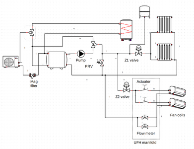
I suppose what I could do is add two three port valves, one for the DHW side (thanks @downfield, much neater) and another one as a buffer bypass. In heating mode the buffer is bypassed on the flow side but remains on the return side, turning into a volumiser. In cooling mode (or maybe never) the pump is in circuit and it operates as a buffer. At least I have both options and it's just one wire to experiment. How does this look?:
(I'll probably take the opportunity to add heat metering while doing it too)
Posted by: @prunusAgreed, you get loss of optimality - but it continues to work, rather than just breaking.
It is very unlikely to break, but of course it just might if there is something unusual about your plumbing. Its obviously your choice whether to (a) take the risk or (b) do it in a way thats reversible or (c) do nothing in relation to this matterother than taking it out of the DHW loop, which obviously you want to do if its going to be used for cooling.
Posted by: @prunusWe get about 40C internally due to east-facing solar gain (external shutters not feasible due to roof and window design). If I'm doing this I want to do it properly, ie get the same smooth constant temperatures for cooling as you get with a heatpump for heating (targeting about 20C). It also needs to be able to fight internal loads (solar gain, electrical equipment, showers, body heat) which makes it harder work than for heating where those things work with you.
OK that's quite a serious endeavour, and a seriously high temperature which TBH, suggests suspect house design (or at least house design that didn't take into account solar gain). However you have what you have.
I cant comment on this level of cooling other than to say that (as you imply may be the case) I am told by those who specialise in commercial aircon that they size for cooling not for heating, because its more challenging. I guess this is because the things that happen in an office (and as you point out also a house) will always heat it but never cool it. You will obviously need to do the same sort of calculations for cooling as you do for heating. In terms of outside air temperature its the same calculation but the adding in the internal loads. I personally have no idea how you calculate for solar gain which is perhaps the dominant effect, maybe someone else does. Are you absolutely sure there is no way to mitigate this at least in part, eg a remotely controlled blind integrated into the window in question, or a projecting shade. In the end it may pay to spend some money on reducing the gain just as it's a good idea to spend money on insulation. Of course I accept this may be impossible.
Common thermostats don't deal with cooling and I don't know if Grant ASHPs control for cooling, or just (like at least some) cool. Sorry I cant help here.
Posted by: @prunusI suppose what I could do is add two three port valves, one for the DHW side (thanks @downfield, much neater) and another one as a buffer bypass. In heating mode the buffer is bypassed on the flow side but remains on the return side, turning into a volumiser. In cooling mode (or maybe never) the pump is in circuit and it operates as a buffer. At least I have both options and it's just one wire to experiment. How does this look?:
The idea of making it switchable seems very sound. If I understand your diagram correctly I think, but am not sure, that the diagram turns it into a kind of three port buffer because there is a third leg not switched by the valves but still connected. A further shut off valve may be needed. Obviously the secondary pump would also need to be switchable.
4kW peak of solar PV since 2011; EV and a 1930s house which has been partially renovated to improve its efficiency. 7kW Vaillant heat pump.
Good spot, I'd missed that 'short circuit' path. Here's another go:
If no V1/V2/V3 are powered (all NC position) then we're in classic buffer heating configuration. The pump runs when there's a call for heat.
V1 is powered (in the NO position) when DHW is demanded. Because V3 is unpowered (in the NC position) the buffer bypass is closed.
If V2 and V3 are powered then the buffer is bypassed. The pump must be disabled.
Possibly also want to drop the Z2 valve if the actuators are going to do the same job, or replace with a manual isolation valve.
How does this look? What else have I missed?
@prunus, @jamespa is correct, but removing the buffer could possibly halve your heating bill, possibly more. You have admitted that you have no idea what the flow rate to your radiators is; therefore, your system is designed by reading tea leaves, not following the laws of thermodynamics. You are moving the heat in to your house with water moving down the pipes to the radiators. If you do not know how much water you are moving, you have no idea if your radiators are reverent too much or too little to satisfy the design. Your statement, " the idea of hydraulic separation is that I don't need to care" could not be more wrong, no flow= no heat energy to the radiator=cold house, very simple.
Balancing and confirming flow rates to radiators was exceptionally difficult, if not impossible in the past, regardless of what plumbers say, today it is simple, there has just been a product launched that you replace the lock-shield with on the return of the radiators, it has a flow meter similar to an under-floor manifold. With this, you can confirm your radiators are receiving the correct flow rate and they will perform to design.
Cooling can be difficult, however, not impossible in a retrofit scenario. Operating with dew-point control does not work in this country due to exceptionally high humidity levels, you need a dew sensor that will control the compressor of the heat pump, but not the pump. If done correctly, it works very well with under-floor heating and fan coils.
You can get the valves here: https://renewableheatinghub.co.uk/the-importance-of-radiator-balancing-for-efficient-heating-introducing-the-flow-regulating-valve/
Director at Heacol | Expert Heat Pump Consultant | Book a one-to-one consultation for pre- and post-installation advice, troubleshooting and system optimisation.
Some fair points... I've been doing some investigations.
The system is balanced, in the sense of delivering heat evenly without cold spots. However while I have the differential outputs adjusted I didn't know the absolute flow (ie everything could be running at 50% of the perfect balance and I wouldn't notice). So here goes some measurements:
- The flow meter on the ASHP primary circuit (28mm piping) says 38 l/min.
- The flow meter on the heating side of the buffer (22mm piping with 15mm drops) with the secondary pump at its current speed (21W and 1.1m3/hr on the display) says 18-19 l/min. All the TRVs are set to maximum so they are wide open. That's in cooling mode (not running the heating in this weather!) with ~18C water.
- If I boost the pump to maximum speed (40W and 1.3m3/hr) the secondary flow goes up to 24 l/min.
- The minimum safe flow according to the ASHP manual is 15 l/min.
I suppose what I should do next is open all the lockshields and remove TRV heads (ie unbalance everything) and see how much flow I can get. There are 10 radiators all with Honeywell Valencia TRVs and matching lockshields.
Having individual flow meters per radiator is no doubt helpful, but not super keen on having to replace valve gear on every rad. I wonder if there's a way to calculate flow from the number of turns of the lockshield or the height of the pin in the existing TRV body (some kind of cap which screws the TRV pin partially down)? There's a flow graph in the Valencia data sheet but I'm not sure how to read it.
However for cooling, unless I fit 10 fan coils or use giant piping I don't think I'm going to be able to achieve the minimum flow rate? So I think I'm still going to need the buffer in that mode?
Posted by: @prunusWhat else have I missed?
Posted by: @prunusSome fair points... I've been doing some investigations.....
The principal reason that heat pumps have minimum flow rate specifications is in order to ensure that heat can be transported away from the compressor. However its no use transporting it from the compressor if it has nowhere to go.
To transport 12kW at a DT of 5C (the usual design value) you need 34l/min. You wont get that easily through a single 22mm primary, max is about 6kW or perhaps 9kW if you push the water speed to 1.5m/s (see cheat sheet here). If you do have a single 22mm primary (and assuming your peak load is actually ~12kW) then some hydraulic separation (and the accompanying penalty) may be inevitable. Better would have been to upgrade the initial few metres of the primaries, but of course this may be disruptive. Alternatively just accepting a higher DT at the heat pump (if the heat pump doesn't complain) might have been be an option. There may be other options, some installers on here claim that they have never found a circumstance where it is necessary to fit a buffer in a domestic situation.
If you have dual 22mm primaries (eg one upstairs, one downstairs) then it is possible to get 12kW through, n which case it suggests either that you have too many valves turned down or that your current secondary pump is inadequate and that the buffer is unnecessary.
I'm hoping that, in your setup and given the primary side flow rate is greater than the secondary side flow rate, the flow to the rads is more or less at the same temp as the flow from the HP, but this depends on the plumbing and internal design of the buffer (which, is rather small for decent stratification). If so then the penalty due to the buffer might be relatively small. If there is a significant drop, which is possible given the small size of the buffer, you will be looking at upwards of 20% penalty, possibly much more as @heacol says.
It would be worth getting to the bottom of this before you decide what to do with your fancoils.
Posted by: @prunusHowever for cooling, unless I fit 10 fan coils or use giant piping I don't think I'm going to be able to achieve the minimum flow rate? So I think I'm still going to need the buffer in that mode
Fancoils have very little water volume and very little resistance. If you have 2*22mm primaries (with the same 15mm drops) you should easily achieve sufficient flow rate. However unless you have sufficient load there may still be nowhere for the energy to go, and because of the low water volume you may need to make up system volume with a buffer/volumiser if either (a) the load is well below the minimum cooling load that the heat pump can turn down (in this case to avoid short cycling) to or (b) you intend to replace the rads with the fan coils and use them for heating also in winter (ditto plus to provide reserve for defrost).
If you are fitting new distribution pipework for the fancoils, it would be a great time to upgrade the distribution pipework for the radiators if its currently insufficient (or better - organise things so its the same pipework).
In summary I think bit more analysis of what you currently have would pay dividends.
4kW peak of solar PV since 2011; EV and a 1930s house which has been partially renovated to improve its efficiency. 7kW Vaillant heat pump.
Hmm, I need to have a crawl around and check the radiator piping but I think it's all one 22mm backbone with 15mm drops - a couple of drops serve two rads opposite sides of a wall. There might be a chance of splitting the 22mm from a single run of 10 to 8+2 or maybe 7+3; I need to take up some flooring to see if I can get an additional pipe run through. DT according to the ASHP seems to be a constant 3C, either in heating or when chilling the DHW tank as a test (both with the secondary pump set to 1.1m3/h (=18l/min), I should try with it at max speed). Installer's heat loss calculation came in at 8kW, and system has glycol in it.
Thinking on fan coils is a completely separate zone, because condensation-proofing any of the existing drops would be a PITA (no rads used for cooling, no fan coils used for heating). UFH manifolds with individual fan coils run from insulated 16mm PB pipe (ie a star arrangement, rather than a backbone). The only fan coil I have so far has 1/2" BSP fittings and the internal pipe is <10mm. I don't want to be pumping around chilled water through fan coils which aren't operating (unwanted cooling and condensation) and in that case I'm not seeing how I can get anywhere near the 15 l/min minimum flow without having a buffer? But switching from having a buffer in the cooling case to being a volumiser in the heating case might be an option.
- 26 Forums
- 2,114 Topics
- 46.4 K Posts
- 28 Online
- 3,410 Members
Join Us!
Latest Posts
-

@eliuccio good to hear you’re happy with the install. A...
By Mars , 16 hours ago
-

RE: Is this just haze or something more?
I am not a scientist nor a meteorologist and I know the...
By Toodles , 1 day ago
-
RE: Benefits of an extra horizontal loop for GSHP
It will improve performance, but by how much depends on...
By Brendon Uys , 2 days ago
-

RE: The good, the bad and the not that great – my heat pump installation
Said I would pop back with a update. Only Mr Jesus h...
By Burtis , 2 days ago
-
RE: Buffers, hot water and cooling
Thats presumably heat pump DT, what about radiator DT a...
By JamesPa , 2 days ago
-
RE: Who's your electricity provider and what's your tariff?
@chandykris Exactly the same here. We now have 13.5kWh ...
By Old_Scientist , 3 days ago
-

Compressor and Evaporator Stratification
I have had a few issues with my Hitachi spilt heatpump ...
By trebor12345 , 3 days ago
-
RE: Wood burner with ASHP - direct air?
This depends on the size of your wood burner and size/t...
By Lucia , 3 days ago
-
RE: Difficult positioning of air source heat pump
@rikiarn It's a not a buffer it's a volumiser which is ...
By Lucia , 3 days ago
-
RE: Is your heat pump insured?
To make things clear, lots of insurance companies cover...
By Lucia , 3 days ago
-
RE: Boxt Heat Pump Installation Experience
@adrian any updates since installation? How is it perfo...
By Ashfp , 3 days ago
-

RE: Say hello and introduce yourself
Hi @seatonian - Yes, I know Seaton, and I have the Nat...
By Transparent , 5 days ago
-

@seatonian got your email. Will connect you with a reco...
By Mars , 5 days ago
-

@downfield and @toddles, this isn’t in the settings cur...
By Mars , 1 week ago
-
RE: Homely launched for Grant Aerona ASHP control
I haven't bought the Aerona Smart Controller (£700!) bu...
By Prunus , 1 week ago
-
RE: Antifreeze top up for my heat pump - is this a rip off?
For the record, Grant supply ethylene glycol for their ...
By Prunus , 1 week ago
-

RE: Compressor attempts start but fails - Nibe Fighter 2005 8kW
@skyefarmer amazing. Well done!
By Mars , 1 week ago
-
RE: Air source heat pump roll call – what heat pump brand and model do you have?
Ebac 5kw - Monobloc R32. Developed and made in UK - Mit...
By marcinwloch69@gmail.com , 1 week ago
-
RE: Is a Valliant Inline 6kW heater a BUS buster?
Just another thought - it might be worth thinking about...
By JamesPa , 1 week ago

