What are the weather compensation settings ? Are you sure the system runs according to these settings ?
Are there internal thermostats at low temperatures that stop the system ? because these operate alongside the WC curve, as an upper limit.
Midea MHCV10WD2N7 R290, 5.8kWp energy community solar power.
Posted by: @pash44pumpExternal pipework is 90mm
I very much doubt that! I am talking about the primary pipework to and from the heat pump, inside the inadequate black insulation. In a 'normal' installation, it will often be 28mm (OD, outside diameter) copper pipe. If you have a pair of calipers, measure the OD, if not improvise something to do the measurement eg dividers or a drawing compass.
While we're on the primary pipework, this photo you posted is rather intriguing - it doesn't even look like copper, more like clear plastic pipe with diagonal reinforcement!
Midea 14kW (for now...) ASHP heating both building and DHW
@tasos There are room thermostats which call for heat from the system. As to whether the system runs according to the WC settings (which are recently added), I don't know yet.
My priority at the moment, is understanding the design of my system, whether it accords to scope and relevant standards and is fit for purpose based on my property. Once I have established that and contacted the installers to start the process of any remedial works, then I will start looking at how exactly the system is running and what to do to improve it via various settings.
Thanks
Posted by: @pash44pumpMy priority at the moment, is understanding the design of my system, whether it accords to scope and relevant standards and is fit for purpose based on my property.
Agreed. The WC and thermostat settings only become relevant when the system is running, which can't that far away now, but we haven't got there yet.
The two current questions are:
(1) OD (and material) of the primary pipework?
(2) is there a formal heat loss survey calculation, and if there is, what does it show?
Midea 14kW (for now...) ASHP heating both building and DHW
@pash44pump I don't know the procedures in UK, but in Greece every property has an energy certificate, which is the starting point for heating/cooling considerations. These are provided by certified energy engineers. Is there something similar in UK ? Because that should be my starting point in your investigation.
Then you should proceed at checking whether the design meets the requirements.
And finally check whether the installation and operation is according to design.
Midea MHCV10WD2N7 R290, 5.8kWp energy community solar power.
@cathoderay of course it's 28mm diameter 🤣 I measured the circumference and didn't do the conversion. Glad someone is awake.
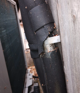
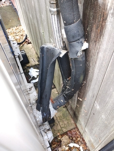
I've attached 2 more photos of the offending pipework, which runs from the heat pump to the isolation valves
Posted by: @cathoderayWhile we're on the primary pipework, this photo you posted is rather intriguing - it doesn't even look like copper, more like clear plastic pipe with diagonal reinforcement!=
So that's the flexible rubber pipe which connects to the back of the external heat pump.
We're looking at the outer stainless steel braid.
The insulation has been arranged so as to channel rainwater into the gap between insulation and pipe.
From there it absorbs the heat and throws it around the base of the heat-pump to keep its feet warm in winter. 🤨
Returning to the set of 14 photos on the previous page, can someone else please clarify that Pic.1 is of the Domestic Hot Water (DHW) tank
and Pic.2 is a buffer tank in a different location?
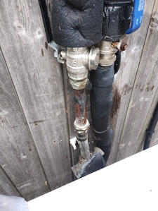
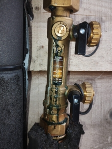
The drips of solder-flux, copper salts and rust residue on the pipes and valves tell me a lot about the standard of work which has gone into this.
Are any of those areas actually leaking?
Or is this just debris left after the installer had 'finished' the job?
I have so much more to write on this, but unlikely to get back to it until tomorrow.
Save energy... recycle electrons!
@pash44pump I don't think piping is the problem (though it may increase running cost). Your pump should be able to deliver max outflow temperature of 60C at -1C outside temperature. This should be more than enough for the UFH. As far as the radiators are concerned, it depends on the radiators. I suppose they are designed for your old oil-fired system, so they may not be adequate. In any, case I would not turn them on, if no one lives there.
All in all, I would bet on the system not being operated properly. Of course for optimal operation, other things could be investigated.
Midea MHCV10WD2N7 R290, 5.8kWp energy community solar power.
Posted by: @transparentSo that's the flexible rubber pipe which connects to the back of the external heat pump.
We're looking at the outer stainless steel braid.
Yes, I see that now, but I wonder what its internal diameter is? A very short length may not matter that much, but longer lengths may impede flow. My line of thinking was that if the primary pipework is in some way insufficient, then it will never be able to transfer enough heat. At least we know that some of the primary pipework is 28mm copper, thanks @pash44pump for that.
For now, I think the key thing is to establish whether there was a formal heat loss calculation or not. If there was, what does it show? If there wasn't, then Sustain Heating and Renewables may find they are in a rather unsutainable position. Let's hope they did do one.
Midea 14kW (for now...) ASHP heating both building and DHW
@pash4pump
Ive looked at the photos and would comment as follows:
The internal insulation seems better than the external, I can see a couple of untaped corners which should be redone but I doubt this is a major issue. My view is that the external insulation should be stripped off and replaced in its entirety.
Internal cabling is a bit of a mess, Im sorry but having suspended cabling as shown in photo 1, unsecured either end, is just slopy in the extreme. Cable ties and cable clips are both easily available to do a proper job.
I cant see any antifreeze valves, but they are often difficult to spot. There should be either a pair of antifreeze valves (the ends of which should NOT be insulated) near the heat pump or the system should be filled with a glycol/water mix, with a strong preference for the first of these. I would check.
Im presuming that the buffer tank is shown in the second photo and the DHW tank in the first.
If Im right then the buffer tank is too small to give adequate stratification (even if it were properly controlled) and thus mixing is inevitable. Given that the load is dominated by the UFH running, presumably, at 35C you potentially have return water from the UFH at 30C mixing with flow water at 50C significantly diluting the flow temperature of the water to the emitters. This is an efficiency nightmare and is hardly going to help performance. I would love to see the design calculations for this side of the for the system, but doubt there are any. My guess is that the installer decided to 'fit a buffer tank so that he didn't have to bother worrying about the existing system', except that he was wrong in thinking that.
The scope document looks fairly comprehensive to me, more than I got in some respects, but it doesn't contain much by the way of design calculations. It would help diagnosis if you could tell us where the heat pump and cylinder are on the plan and which rooms are the coldest. Also at what temperature does it become inadequate and by how much?
My strong suspicion (little more than an educated guess based on what we know so far) is that you have a significant drop in temperature between heat pump and UFH pipework due to the combination of buffer tank, long pipework and pipework with poor insulation and the mixing valves, exacerbated by not having the rads on upstairs and the interaction with room thermostats which probably turn off flow to sections of UFH when it should be on. As a result the UFH is not receiving water constantly at the design temperature, causing your shortfall. Its also possible that the flow rate through the UFH is insufficient, leading to a higher DT than ideal, reducing the average temperature and thus heat transfer from UFH pipes to screed. With the boiler, running at perhaps 55-75C, some of this would still have happened but been masked because of the high starting temperature.
Some temperature measurements combined with neutralising the external controls by turning them to max, will confirm or deny my suspicion, but of course only once we get to the heating season.
To help with diagnosis it might be worth finding out how the UFH controls and heat pump controls are connected (if indeed they are). A common way to do things when there is a buffer is not to connect them, which for the installer has the advantage that they don't have to touch the existing control system. In this arrangement the call for heat derived from the room thermostats turns the UFH pump(s) on/off drawing warm water from the buffer tank and replacing it with cool. Totally separately the heat pump monitors the buffer tank temperature and tops it up when it goes below a certain value. If it is wired like this then it explains your summer behaviour.
Hope that helps
4kW peak of solar PV since 2011; EV and a 1930s house which has been partially renovated to improve its efficiency. 7kW Vaillant heat pump.
Referring to an early point, night time firing could be caused by legionella precautions, could it not?
Midea MHCV10WD2N7 R290, 5.8kWp energy community solar power.
To summarise where things stand.
The external insulation is totally inadequate and should be completely replaced and I will contact the installers to demand that they do this using the guidelines provided by @transparent (and hopefully they respond so that I don't have to go through one of NICEIC, MSC or HIES, all of which the installer is a member of). This is my number one priority.
We need the Formal Heat Loss calculations in order to understand the design better. I have asked the installer for those today.
It appears the buffer tank is too small and this element of the design is probably running inefficiently (plus a number of other reasons). It would be good to understand how the buffer tank is wired as per @jamespa's comments. I can ask the installer if they can shed light on this. I assume this is isn't something that can be diagnosed remotely?
More investigation is clearly needed in how to run the system but there are still some design questions to understand before we get to there and experiments will be better run when the ASHP is needed for heating, which should be soon.
So I will be contacting the installer regarding the insulation, but is there anything else that should be flagged as a design fault at the same time? I guess I should wait until they respond regarding Formal Heat Loss calculations before I list my issues.
In terms of outstanding questions from various posters:
(1) I believe the presence of a large container of glycol suggests that there are no antifreeze valves. I assume this is an installer decision that might be sub-optimal but something I have to live with.
(2) Are there any leaks? Yes there is a small amount of leakage from the pipework in the following photo. What actually are those valves? How big an issue is this? I would raise this with the installer as another thing that needs resolving.
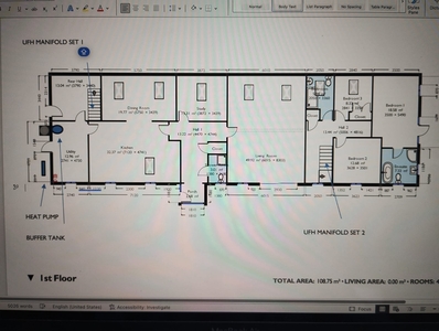
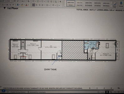
(3) Regarding system positioning and historical performance issues, I attach photos of the ASHP position, the buffer tank position, the DHW tank position and the position of the 2 sets of UFH manifolds.
You won't be surprised to know that the worst performance in the house are bedroom 1 and its en-suite. They are furthest from the ASHP and also are some of the only rooms that have 2 external walls. They face down a valley, from which all the winds and rain come, making this the coldest end of the house even with no heating on. At the moment for example, with no heating on, the kitchen end of the house is 21.5C and those rooms are at 20C.
During cold periods, those rooms have been as low as 12C when the external temperature has been below 0C. Bear in mind that I had always been running on set flow temperature not WC and with radiators off.
You should also know that the house has multiple zone thermostats (as it did when we bought the house) which are wired into the UFH manifolds to call for heat, when the temperature of a zone drops below desired temperature. Some posters have mentioned room thermostats as being negative but in a large house, how else do you control the temperature of zones that you don't want to be the same. As you can see in the scope document, the desired bedroom temperatures are 3-4 degrees below that of kitchen/study etc.
Before I go back to the installer (and I would like to see @transparent's comments to the scope document which he said he might get to tomorrow) is there an issue with the stainless steel braided flexible pipe as an outlet from the ASHP or is it just a question of poor insulation? Also, should the pipework be inside (which it quite easily could be)? Given that I've had 4 years of badly-insulated pipes, I think it's the least they should do. Should I treat the external pipework overhaul as a separate question to any internal design issue?
Many thanks all
- 27 Forums
- 2,495 Topics
- 57.8 K Posts
- 208 Online
- 6,220 Members
Join Us!
Worth Watching
Latest Posts
-

RE: Electricity price predictions
@transparent Triggered by the various commen...
By JamesPa , 18 minutes ago
-

RE: Solis inverters S6-EH1P: pros and cons and battery options
Just to wrap this up here for future readers: The S...
By Batpred , 48 minutes ago
-
RE: Struggling to get CoP above 3 with 6 kw Ecodan ASHP
Welcome to the forums.I assume that you're getting the ...
By Sheriff Fatman , 55 minutes ago
-

RE: What determines the SOC of a battery?
I agree. Fogstar confirmed that the Seplos BMS does ...
By Batpred , 1 hour ago
-
RE: Humidity, or lack thereof... is my heat pump making rooms drier?
I've found that generally the humidity in the house is ...
By IRMartini , 2 hours ago
-
RE: Say hello and introduce yourself
@editor @kev1964-irl This discussion might be best had ...
By GC61 , 2 hours ago
-

RE: Testing new controls/monitoring for Midea Clone ASHP
@benson — as @tasos suggests, plotting multiple variabl...
By cathodeRay , 5 hours ago
-

@painter26 — as @jamespa says, it's for filling and re-...
By cathodeRay , 6 hours ago
-

RE: Oversized 10.5kW Grant Aerona Heat Pump on Microbore Pipes and Undersized Rads
@uknick TBH if I were taking the floor up ...
By JamesPa , 17 hours ago
-

RE: Getting ready for export with a BESS
I would have not got it if it was that tight
By Batpred , 19 hours ago
-

RE: Setback savings - fact or fiction?
I also need to correct something I said by mistake earl...
By cathodeRay , 19 hours ago
-
RE: Need help maximising COP of 3.5kW Valiant Aerotherm heat pump
@judith thanks Judith. Confirmation appreciated. The ...
By DavidB , 22 hours ago
-

RE: Recommended home battery inverters + regulatory matters - help requested
That makes sense. I thought better to comment in this t...
By Batpred , 22 hours ago
-
Bosch CS5800i 7kW replacing Greenstar Junior 28i
My heat pump journey began a couple of years ago when I...
By Slartibartfast , 22 hours ago
-

RE: How to control DHW with Honeywell EvoHome on Trianco ActiveAir 5 kW ASHP
The last photo is defrost for sure (or cooling, but pre...
By JamesPa , 24 hours ago
-

RE: Plug and play solar. Thoughts?
Essentially, this just needed legislation. In Germany t...
By Batpred , 1 day ago
-
RE: A Smarter Smart Controller from Homely?
@toodles Intentional opening of any warranty “can of wo...
By Papahuhu , 1 day ago
-
RE: Safety update; RCBOs supplying inverters or storage batteries
Thanks @transparent Thankyou for your advic...
By Bash , 1 day ago
-
RE: Air source heat pump roll call – what heat pump brand and model do you have?
Forum Handle: Odd_LionManufacturer: SamsungModel: Samsu...
By Odd_Lion , 1 day ago
-
RE: Configuring third party dongle for Ecodan local control
Well, it was mentioned before in the early pos...
By F1p , 2 days ago
-

RE: DIY solar upgrade - Considering adding more panels
I know this is a bit old, but it made me wonder what co...
By Batpred , 2 days ago
-

RE: New Vaillant aroTherm Plus in black - When will it come to the UK?
@majordennisbloodnok Daikin, take note! (In fact, I hav...
By Toodles , 2 days ago
-

RE: Midea ASHP – how to set weather compensation
@mk4 — good work! First, I agree, no evidence of cycl...
By cathodeRay , 2 days ago

