I've found something out that might be significant. I remembered something the installer said to me about a part being missing (bear in mind this was 18 months ago). He said he'd got a similar one and installed that. When the actual part arrived he gave it to me in a box, I had no idea what it was. It's been sat under a pile of stuff ever since so I went and dug it out.
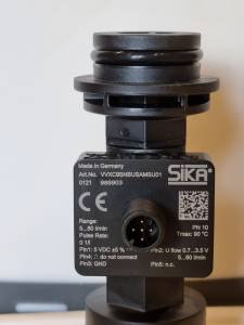
Guess what, it's the flow sensor (Art.No. VVXC9SNBUSAMSU01)
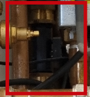
The one they installed is very hard to see but with the help of a mirror and my phone I managed to get a shot of it. Its Art.No. is VVX20MITSUBISH08. Clearly this was meant for a Mitsubishi heat pump. It's very similar but technical details for pin 2 (as printed on the back) are different.
Samsung:
Pin2: U flow 0.7 ...3.5 V
5...60 l/min
Mitsubishi:
Pin2: U flow 0.5 ...3.5 V
5...100 l/min
Could this be causing the problem or does it not matter? My other thought is that when an installer 'gets one out of the van' it often a broken one from a previous job (I've had that before).
Will post flow diagram shortly, sorry for the delay.
@riponowl so the samsung thinks the flow is 13 lpm right?
I've just done the maths on the voltage vs flow rate readings that would come out of the of the two meters, as per your figures above. You just do a linear interpolation on the voltage vs flow rate numbers . I think this means you are getting 1.10V, based on a samsung HP thinking you've got 13lpm. this voltage would correspond to 24lpm on a mitsu meter.
given that you actually have a mitsu meter, that means the flow rate is (approx) 24lpm. but you have a samsung HP so it interprests 1.1V as being 13lpm. so (it would seem) you don't have a flow rate problem per se, with your system you have a flow rate measurement-and-reporting problem.
the issue is still that if the flow rate were to drop at all, the samsung HP would think that the flow rate is less than its minimum (12lpm) and shut down.
IMO you need to get your heating engineer to swap the flow meters. Or hack the voltage with some DIY electronics???
My octopus signup link https://share.octopus.energy/ebony-deer-230
210m2 house, Samsung 16kw Gen6 ASHP Self installed: Single circulation loop , PWM modulating pump.
My public ASHP stats: https://heatpumpmonitor.org/system/view?id=45
11.9kWp of PV
41kWh of Battery storage (3x Powerwall 2)
2x BEVs
Thank you Ian & Derek.
It certainly seems like the flow reading on the Samsung controller screen is incorrect. The Sontex is giving me a reading of 24 lpm so I am going to assume that to be the correct one. My main concern now is that I sometimes see a reading as low as 12.3 lpm which is not far off the system shutting down. Unfortunately the flow meter is in a very difficult location to reach, inside a tight space in a cupboard behind other pipework. It's yet another black mark against my awful installers and the chances of them coming out to fix it are as good as zero.
I promised a diagram so I'll attach it here in case anything else comes to mind. I've tried my best to make sure it is correct, however if you see something that looks wrong let me know and I will go and double check.
@riponowl my sympathies on dealing with what seems a very difficult to access install. if there is another location in the pipework that is more easily accessible, then you could put the samsung flow meter there, and just ignore the mitsu meter, leave it in the pipework but not connected to anything. put the samsung on a fresh piece of straight pipe, if you can identify a suitable spot, then wire that into the samsung controller instead of the mitsu one. the plumbing bit is a job that any competent plumbing and heating engineer can do, they don't need to be a heat pump specialist. the wiring bit is blindingly obvious. but you obviously have to take your system down to do it.
although - if not doing a swap, you would need the two special connectors, that come with the flow meter, that connect it to standard pipe size fittings - do you have those?
If this was done under MCS, then you have grounds for attempting to get MCS to make your installer remediate it, although I' m sure you are already well aware that is not a road that is easy to travel.
looking at your diagram - first of all congrats its very clear. I am still puzzled why there are two pumps! the topology you have , which is a single loop, is usually done with one. and it sounds like your house is not large enough to have any reason to justify two in series. you've just got two pumps that can go wrong instead of one...It also stops you from being able to do variable pump speed control (which can improve efficiency). But again, simplifying to a single pump would require taking your system down.
one other thing to note - you have an ABV. That is not needed if you are running an open circulating loop with a large group of radiators "always open", as there is always a path for the water to flow through. ABV's are a hangover from boiler designs with TRV's everywhere, where its possible for no radiators to be open. Again if you were to have the plumbing modified, the ABV connection should be got rid of. For the moment, close the ABV to its highest pressure setting. However its still possible that it is could be opening even at that setting : does the pipe get warm on its "left" side as per your diagram? . If it does open it will cause you inefficiency issues.
My octopus signup link https://share.octopus.energy/ebony-deer-230
210m2 house, Samsung 16kw Gen6 ASHP Self installed: Single circulation loop , PWM modulating pump.
My public ASHP stats: https://heatpumpmonitor.org/system/view?id=45
11.9kWp of PV
41kWh of Battery storage (3x Powerwall 2)
2x BEVs
Great sketch also of the pipework @riponowl
@iancalderbank has great knowledge of your brand of HP so I’ll keep my comments to pipes and rads.
As yet I don’t think we have found out your radiator (emitter) sizes. But for now I have substituted an assumption-they have a DT50 rating of 1.2 kwh each giving an assumed capacity of 8.4kWh. This is only a temporary guess of what would work. This needs replacing with actual size asap.
IDEALLY your primary flow and primary return pipes should branch off at a 35mm tee then each branch reduced to 22mm.
That would mean that you could have your 7 radiators split over 2 separate branches of the same loop.
Your pipe sizes, as drawn, would have limited heat carrying capacity since the rads flow and return pipes appear to be all supplied in 15mm pipe in a linear distribution. That means all the heat from your HP has the containment of a single 15mm flow.
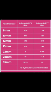
As mentioned, a 15mm pipe can only carry 2.75 KWh of heat at DT 5. And a single 22mm pipe can carry 6kw at DT5. So if you had 2 x 22mm branches feeding the radiators you would have a potential heat carrying capacity of 12kwh at DT5. (and considerably more at DT7)
Having said that your other limiting factor may be the capacity of your 7 radiators. Can you indicate the DT50 rating of your radiators? Or size and model ref.
I’ve attached a pipe chart from Heat Geek showing heat carrying capacity of different sizes of Pipe at the 2 DeltaT ranges.
hope this helps
Thanks again for your responses.
Ian:
I'd never thought of putting the Samsung meter elsewhere, that is a good idea. I do have the connectors, strangely they are each attached (separately) to a short length of pipe, like they have been removed previously. I have no memory of that but the install was 18 months ago. The really frustrating thing is that I had the system drained down not so long ago, I'm kicking myself now for not having this conversation sooner.
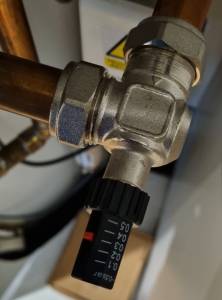
I identified the components on the diagram by taking a photo and doing a reverse image search, so hopefully I've identified the ABV correctly but just in case I haven't here is a photo.
I'm not sure how it works or how to adjust it. The pipe to the left (as per diagram and photo) does warm slightly but its only 10cm to the 'main' pipe so I'd guess that's to be expected?
SUNandAIR:
I think this is an error on my part. I got carried away and included the radiators on the diagram but I have absolutely no idea how they are plumbed in. All I know is that the pipes that come from the floor/ceiling are 15mm but without taking the floor up I can't tell what the configuration is. I have the details of the radiators somewhere I will find that information out and post it later.
Addenda: The heat pump is currently heating the water and the pipes both sides of the ABV are hot.
I suspect that your diagram is not correct with regard to the piping of the radiators.
Your diagram shows the radiators connected in series using 15mm pipework, but I think that you will find in practice the radiators are connected in parallel using 15mm pipes fed from a 22mm flow pipe to a 22mm return pipe.
Your diagram should actually show a 22mm pipe (flow) running down one side of all the radiators, with a 15mm pipe connected to one side of each radiator. Another 22mm pipe (return) should be on the other side of the radiators, again connected to each radiator by a 15mm pipe. This arrangement allows the water to flow through each radiator without any form of restriction and thereby supply the full thermal energy to your home.
In your present diagram, if a TRV were to close on one radiator, it would stop the flow through all the radiators.
Posted by: @riponowlAddenda: The heat pump is currently heating the water and the pipes both sides of the ABV are hot.
its really hard to prove this one, because with an ASHP the difference between Flow and Return T is not a lot, not always easy to feel, and the behaviour of the heat depends on how long the run from the T points though the ABV is, and even the physical layout (up/down/sideways, bends or not). So it can be conduction or convection not necessarily water flowing through the ABV...or it can indeed be the ABV opening. letting it go cold and monitoring with a hand how fast the cool side warms up may give you a clue if its opening. But I suspect it probably is. which is really bad for efficiency.
anyway there is loads of stuff on the net about how to set an ABV. you just want to set it to the highest possible opening pressure (maximum resistance to being opened), which I think will be the 0.6bar setting on yours, but that may well perhaps still be pushed open by your two pumps 🙁 If you are draining down, you just remove the ABV and block off that cross-link.
your radiators if they are any sensible modern system will not be 1 pipe in series, they will be 2 pipes with the rads across them as per derek-m. Google "1 pipe vs 2 pipe radiator system". 15mm to the rad itself is ok - but if it all joins up into a single 15mm to get into the airing cupboard, then its undersized. It has to be at least 22mm by the point the rads all join back together into the airing cupboard.
If you do in fact have all rads on a common 15mm then that could , bizzarely, explain why you have two pumps - they've put in an overkill amount of pump head to compensate for the head loss imposed by pushing through a single 15mm 🙁
feel free to post a photo of the pipework connectors for the flow meter.
My octopus signup link https://share.octopus.energy/ebony-deer-230
210m2 house, Samsung 16kw Gen6 ASHP Self installed: Single circulation loop , PWM modulating pump.
My public ASHP stats: https://heatpumpmonitor.org/system/view?id=45
11.9kWp of PV
41kWh of Battery storage (3x Powerwall 2)
2x BEVs
-
Flow Rate & Low Loss Headers
8 months ago
-
Primary Pump positioning for Samsung Gen6 system
1 year ago
-
Training videos/course/whatever. Control settings
2 years ago
Currently viewing this topic 3 guests.
- 27 Forums
- 2,495 Topics
- 57.8 K Posts
- 899 Online
- 6,220 Members
Join Us!
Worth Watching
Latest Posts
-

RE: Humidity, or lack thereof... is my heat pump making rooms drier?
That’s my pleasure, @andrewj. The only challenge now is...
By Majordennisbloodnok , 44 minutes ago
-
RE: Electricity price predictions
@toodles @skd Then there is not going to be much from t...
By ChandyKris , 1 hour ago
-
RE: Solis inverters S6-EH1P: pros and cons and battery options
@batpred I reckon Andy might know a thing or 2 about...
By Bash , 2 hours ago
-
RE: What determines the SOC of a battery?
@batpred Ironically you didn't have anything good to...
By Bash , 3 hours ago
-
RE: Testing new controls/monitoring for Midea Clone ASHP
Here’s a current graph showing a bit more info. The set...
By benson , 3 hours ago
-
RE: Setback savings - fact or fiction?
True there is a variation but importantly it's understa...
By RobS , 3 hours ago
-

Below is a better quality image. Does that contain all ...
By trebor12345 , 4 hours ago
-
Sorry to bounce your thread. To put to bed some concern...
By L8Again , 4 hours ago
-

@painter26 — they (the analogue gauges) are subtly diff...
By cathodeRay , 4 hours ago
-
Our Experience installing a heat pump into a Grade 2 Listed stone house
First want to thank everybody who has contributed to th...
By Travellingwave , 8 hours ago
-
RE: Struggling to get CoP above 3 with 6 kw Ecodan ASHP
Welcome to the forums.I assume that you're getting the ...
By Sheriff Fatman , 11 hours ago
-
RE: Say hello and introduce yourself
@editor @kev1964-irl This discussion might be best had ...
By GC61 , 12 hours ago
-

RE: Oversized 10.5kW Grant Aerona Heat Pump on Microbore Pipes and Undersized Rads
@uknick TBH if I were taking the floor up ...
By JamesPa , 1 day ago
-

RE: Getting ready for export with a BESS
I would have not got it if it was that tight
By Batpred , 1 day ago
-
RE: Need help maximising COP of 3.5kW Valiant Aerotherm heat pump
@judith thanks Judith. Confirmation appreciated. The ...
By DavidB , 1 day ago
-

RE: Recommended home battery inverters + regulatory matters - help requested
That makes sense. I thought better to comment in this t...
By Batpred , 1 day ago
-
Bosch CS5800i 7kW replacing Greenstar Junior 28i
My heat pump journey began a couple of years ago when I...
By Slartibartfast , 1 day ago
-

RE: How to control DHW with Honeywell EvoHome on Trianco ActiveAir 5 kW ASHP
The last photo is defrost for sure (or cooling, but pre...
By JamesPa , 1 day ago
-

RE: Plug and play solar. Thoughts?
Essentially, this just needed legislation. In Germany t...
By Batpred , 1 day ago
-
RE: A Smarter Smart Controller from Homely?
@toodles Intentional opening of any warranty “can of wo...
By Papahuhu , 1 day ago
-
RE: Safety update; RCBOs supplying inverters or storage batteries
Thanks @transparent Thankyou for your advic...
By Bash , 2 days ago
-
RE: Air source heat pump roll call – what heat pump brand and model do you have?
Forum Handle: Odd_LionManufacturer: SamsungModel: Samsu...
By Odd_Lion , 2 days ago
-
RE: Configuring third party dongle for Ecodan local control
Well, it was mentioned before in the early pos...
By F1p , 2 days ago


