You are indeed correct, it may depend upon what the water pump(s) are doing.
I know that some of the heat pump controllers continue to run the water pump for a number of minutes after the compressor and fan(s) have stopped, and may also periodically operate the water pump for several minutes to equalise the water temperature around the heating system.
From observing my own heating system, it takes approximately 4 minutes to heat the radiators to the temperature calculated by the controller, after which the boiler and water pump is stopped. During colder weather conditions the required radiator temperature may be in the 40C to 45C range, and it may only take 10 to 15 minutes for the radiator temperature to reduce by approximately 5C, at which point the boiler and water pump is restarted. During milder weather conditions the radiator temperature may only need to be in the 30C to 35C, so it may then take 30 to 60 minutes for the radiators to cool sufficiently for the boiler and water pump to be restarted.This keeps the IAT at 21C +/- 0.2C under all conditions.
The point I was trying to make is that the location of the LWT and RWT sensors is very important, particularly if the water pump(s) do not run continuously when the heat pump is no longer producing thermal energy. Continuously operating the water pump to prevent the LWT and RWT sensors cooling too quickly probably would reduce the cycling frequency, but would use more electrical energy and may also transfer thermal energy from indoor to outside. I'm not certain if any controllers operate in this manner. It would be interesting to see how the different heat pumps control their water pumps and also the actual location of the LWT and RWT sensors, and the effect this may have upon the frequency at which cycling takes place.
As I have stated previously, one possible way to reduce cycling frequency could be to set the WC curve such that it causes the IAT to start to increase before the heat pump reaches the point when frequent cycling is likely to occur, and then use a room thermostat to start and stop the heat pump rather than the LWT and RWT sensors.
All Modern Heat Pumps will Cycle when operating BELOW the Minimum Inverter Power .
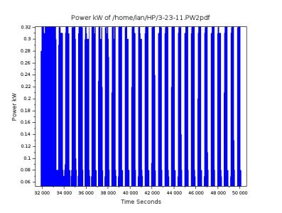
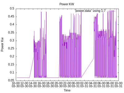
Here is a detailed graph of the Power my Heat Pump consumed during the evening of 23-March-24.
The Cycling Time, Run_Time ( Mark *) + OFF_Time ( Space *) = ~ 10.12 Minutes.
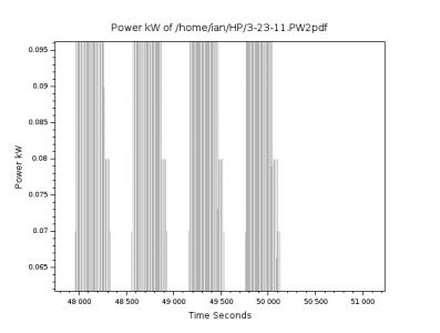
Here is a more detailed Graph of the Power consumed during the evening of 23-March-24, showing the Run Times.
The instantaneous RUN Time is , here, ~5.0 Minutes.
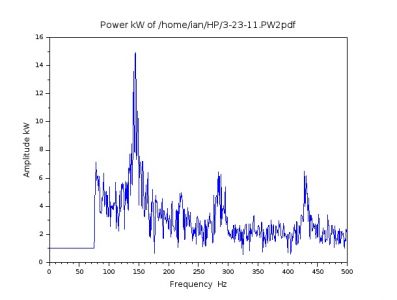
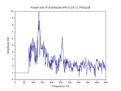
Here is the FFT of the Power consumed during the evening of the 23-March-24 , showing the Cycling Frequency.
The Frequency Maximum , here provides an Average Cycling Time of 9.96 Minutes.
The First Harmonic of the Cycling Frequency provides a Check, giving a 5.03 Minutes.
The RUN TIME CALCULATION **
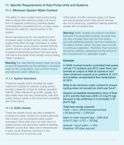
My Heat Pump has a 50 Litre Buffer Tank fitted Across the output ports of my Heat Pump.
When Operating Below the Minimum Inverter Power of 2.5 Kw my Heat Pump is Cycling.
The Energy input into the Buffer Tank , when operating at the Inverter Minimum Power , kWh = Minimum_Power ( kW ) X Run_Time (Seconds)
The Energy Input Heats 56 Litres of Water to the Temperature Difference Across the Buffer, Delta_T .
The Energy Required to Heat 56 Litres of water to a Temperature of Delta_T is:
Energy Required to Heat 56 Litres of Water to ~4C = 4.18 X 50 X 4
Therefore, the 2.5 kW Minimum Power X Run_Time = 4.18 X 50 X 4
Therefore, Run _Time ( Seconds ) = (4.18 X50 X 4 ) /2.5 Seconds.
OR
Run_Time = (4.18 X 50 X 4 ) /(2.5 X 60 ) Minutes.
My Calculated Run_Time is Therefore , 5.57 Minutes
My Instantaneous Measured Run Time is ~5.00 Minutes.
My Average Cycle Time ( from FFT ) is 9.96 Minutes.
My Average Run_Time ( from FFT ) is 5.03 Minutes.
Is my Heat Pump STILL Short Cycling ?
* Sorry to use the Electrical Mark to Space Ratio Terminology
** Check the MCS Calculations in :
All Modern Heat Pumps use an Inverter to control Heat Pump Water Power.
All modern Heat Pumps have a Minimum Power BELOW which the HEAT PUMP WILL REVERT to Cycling.
The DECC, in 2012, produced a Report on the Effects of Cycling on the Heat Pump COP:
The DECC Report was produced at a time when Heat Pumps with Inverter Power control were in their infancy.
The Report is however still useful when operating an Inverter Heat Pump BELOW it's Minimum Inverter Power.
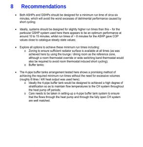
The Reports Recommendations are shown in the following :
Recommendations:
1) Recommended that Air Sourced Heat Pumps should be designed for a Minimum Run Time of 6 Minutes.
2) Run Times of ~ 8 Minutes gave COP Values close to the "Catalogue" Steady State Values.
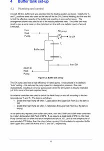
3) 4 Pipe Buffer Tanks show a promising method of achieving the required Minimum Run Times without the need for "Excessive Buffer Volumes".
The Buffer here used was a Buffer fitted Across the Output ports of the Heat Pump :
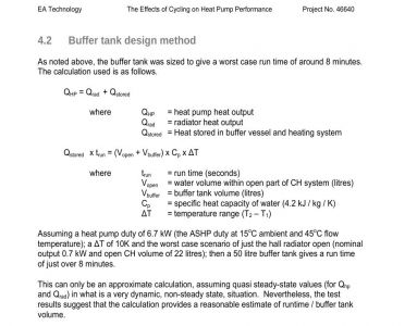
Note also the Calculation of the Size of Buffer required:
Further note that these calculations are for an older control system, but , none the less valuable in the demonstration of a Buffer Tank fitted Across the Heat Pump Water output.
Also note that by present standards, Very Poor COP that were achieved.
Why can't Heat Pumps be Mathematically DESIGNED and tested using a program like H2X ??
Buffers as Batteries?
With the introduction of Timed Low Cost Tariffs , e.g. Octopus "Cosy" , Buffer Tanks/Volumisers can now be used to Store Energy during "Cheap periods" for use during more Expensive periods.
Buffers as Back-Up Heaters?
During winter, I need a Back-Up Heater for Only four weeks per year.
To meet this Limited Requirement I could either
Install a new, larger, Heat Pump
OR
Install a couple of Immersion Heaters into my Buffer Tank.
My Samsung already has a complete Back-Up Heater for just such a Requirement.
"Short Cycling ", Water Volume and Heat Pump Sizing?
My Heat Pump continues to "Short Cycle " with a RUN TIME period of ~ 5 Minutes.
The DECC Report says that Heat Pumps should NOT be designed for a RUN TIME of Less than 6 Minutes!.
Both Cycle Times and RUN _Times are determined by the Volume of Water within the pipe system, AND, the Minimum Inverter Power from the Heat Pump.
If the Volume is insufficient then a Buffer Tank/Volumiser should be installed.
If the Minimum Inverter Power is Too large then a Smaller Heat Pump would be required.
A smaller Heat Pump would, however, require a Back-Up Heater during Winter!
P.S Why can't Heat Pumps be Mathematically DESIGNED and tested using a program like H2X ??
@derek-m The carel controller in my ASHP allows me to specify three pump modes: Normal, Demand, Continuous...
Normal - pump shuts off when setpoint is reached. Use this when driving a buffer tank.
Demand - pump will 'sniff' for a bit to see if the water in the circuit has dropped below the setpoint. No idea when you'd use this mode.
Continuous - pump runs whenever the call-for-heat is active. Compressor/fan come on as required under the control of the PID in the heat pump.
I use mine in continuous mode as I only have the single pump and I don't have room stats.
Off grid on the isle of purbeck
2.4kW solar, 15kWh Seplos Mason, Outback power systems 3kW inverter/charger, solid fuel heating with air/air for shoulder months, 10 acres of heathland/woods.
My wife’s house: 1946 3 bed end of terrace in Somerset, ASHP with rads + UFH, triple glazed, retrofit IWI in troublesome rooms, small rear extension.
Design & Measurements of Heat Pump Performance?
Wall Thermal Conductivity, U ...............abuse ?
Given my own experience, where my "installer" Altered the Wall Thermal Conductivity to justify the use of a particular Heat Pump Can I again ask the Question :
Why are Thermal Wall Heat Conductivities NOT Measured ?
Measurement would require the use of a standard Electric Fire attached to a Power Meter with TWO Thermometers , One indoor, the other Out Side.
From Experience, measuring U is far more accurate and Untainted by installer behaviour.
Measurement of the Performance of Heat Pumps?
Heat Pump Performance should be measured with an in -Water Power Meter !
Heat Pump Performance , COP should be Measured at the Start of the Piping System AND NOT at the Heat Pump itself.
Design
Heat Pump Systems should be designed with a Thermal Software e.g. H2x .
Measurements against the design?
Having completed a Software design the Performance MUST be tested against the Design!
Any deviations between the Design and Performance will bolster customer Confidence.
p.s. As William Thomson, Lord Kelvin , said " if ye canny Measure it .....ye don't understand it"
My Heat pump REAL COP ( that measured at the start of the Radiator pipe circuit ) and Heat Pump COP ( as shown by the Heat Pump itself ) are for 28/29 March:
-- Attachment is not available --
My REAL COP is therefore , circa 2.2 , while my Heat Pump COP is circa 2.9.
The Difference between My REAL COP and the Heat Pump COP is reflected in the Energy loss between the Heat Pump and my house:
-- Attachment is not available --
The Average Loss is therefore circa 26% without using the HOT WATER TANK.
"Short Cycling" is shown in the FFT of the Heat Pump Power consumption :
-- Attachment is not available --
With the Peak representing a Cycle Time of circa 10.11 minutes.
Peak Frequency = 157 Hz on a run of 95274 Seconds duration gives a Wavelength of ~95274/157 Seconds , or ~10.11 Minutes.
The Run Time is shown in the following :
-- Attachment is not available --
With the RUN Time here of 4.5 Minutes.
Conclusions:
1) With the DECC Report recommending a Minimum 6 Minute RUN TIME My Heat Pump is "SHORT CYCLING".
2) With the DECC Report recommending a Minimum 16 Minute CYCLE TIME My Heat Pump is "SHORT CYCLING".
Measuring Cycle and Run Times on a Heat Pump
I record the Power Consumed by my Heat Pump on a Daily basis.
For example , on 30 th March I get:
Clearly, my Heat Pump is suffering from "Short Cycling". The Question is "How Much"?
I can examine the "Short Cycling by taking the Fast Fourier Transform :
But , again , the "Short Cycling " , although much more prominent , with a peak at ~150 Hz , is still very Noisy!.
Also, the Run Time component of the cycle time is completely lost in the Noise!
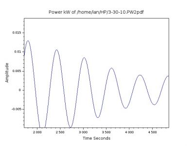
Using the FFT as a filter for the Cycle Time gives:
Now a beautiful Noise free Sinusoid giving the exact Cycling Time as 10.12 Minutes!
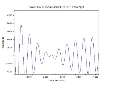
On using the FFT as a filter for the RUN TIME :
Again a Beautiful Noise free Sinusoid giving the exact RUN TIME as 4.3 Minutes.
All Graphical work was performed using "SCILAB " on a LINUX PC.
Many congratulations to "Dassault " in France for rebuilding Scilab after a absence of Three Years!
Scilab will , probably work on "Windows" , probably!
ian
Is my Heat Pump Too SMALL for Winter AND TOO BIG for Spring?
My Heat Pump does Not supply ENOUGH Power HEAT DURING Winter .
-- Attachment is not available --
Notice the HEAT PUMP is permanently ON , Controlled by the Inverter.
My Heat Pump does Supplies TOO MUCH Power IN Spring!.
-- Attachment is not available --
Notice the HEAT PUMP is "Short Cycling" , Controlled under Cycling !.
The RANGE of the Inverter , between Minimum Inverter Control and Maximum Inverter Power is TOO SMALL!
The Solution Would be to provide a Backup Electric Immersion Heater inside my Volumiser Tank.
Why Do Manufacturers NOT Provide the MINIMUM AND MAXIMUM INVERTER POWER?
Heat Pumps: Hypothermia & Bankruptcy
Having spent ~£14k on a Heat Pump I am now , a 76 year old , Am I Now faced with Heat Pump Hypothermia ?:
-- Attachment is not available --
My "Installer" has now been STUCK-OFF for the THIRD TIME with the NIC making the comment that
" YOU ARE NOT GOING TO LIKE THIS ........................BUT NOTHING CAN BE DONE "
The NIC have said that they are "Sorry" but that they have exhausted their efforts by the application of Further SANCTIONS against my "installer".
My Blood pressure is , on average, over the Winter 155/84 as shown in the following graph:
-- Attachment is not available --
I am paying ~£165 per month for the running costs of this Heat Pump !.
I am paying ~£42 per month for the "loan " repayment for a "Drawdown " Payment for this Heat Pump!
Heat Pumps: Hypothermia & Bankruptcy
Frenchmen, Germans and Blushing Heat Pump "Engineers!"
Over the past two years, visiting "Engineers" have produced the most extraordinary comments .
A visiting French Samsung "Engineer" produced the following classic:
"Only the Germans REALLY Understand How Heat Pumps work!"
A visiting Blushed to the roots of his hair saying to his colleague :
" Perhaps you cannot set the Water Temperature because of what is being displayed on the Front Screen !"
The Blushing "Engineer" had previously been found to have falsified my house Energy requirements to justify the installation of the wrong heat Pump.
Another "Engineer" said that :
"WE will Repair and , if necessary replace your Heat Pump IF YOU AGREE TO THE REMOVAL OF ALL METERING". I Declined the offer.
A visiting NIC "Engineer" said that "I , the user, should NOT INTERFERE WITH THE SETTINGS INSTALLED BY MY INSTALLER ".
A Visiting TRIO OF ENGINEERS , including a NIC Engineer succeeded in completely stopping my Heat Pump when trying to simultaneously set the Water Temperature using "Weather Compensation " AND Explicitly set the water Temperature using the Heat PUMP Field bit settings" :
" Long Silence ........" followed by the comment that " You, ( ME The USER ) HAVE INTERFERED WITH The Settings of the previous French Heat Pump "Engineer".
I reset, the , now faulty, Heat Pump about 30 minutes after the Trio left with their tails between their legs.
Finally, A visiting Father & Son pair of "Engineers" :
Father , Shouting : " I have never, in 30 Years experience with Heat Pumps ever installed a buffer Tank......."
Son , Quietly : " I am well aware that fitting a Buffer Tank is used to reduce the excessive "Short Cycling" that you clearly have experienced , my only comment would be the Size and position of the Buffer/Volumiser tank".
Why Do some, ( MOST !) "Heat Pump Engineers" , have such a low opinion of themselves , their industry, and their fellow competitor "Engineers"?
It's a bad day for buffer tanks. @heacol is officially the Head of Domestic Heat Pump Design Net Zero at British Gas. He's tasked with getting BG engineers to improve design and installation quality. It's a big move on Brendon's part, and hopefully, one that will lead to a speedier transition to higher ASHP installation quality on a mainstream basis.
Get a copy of The Ultimate Guide to Heat Pumps
Subscribe and follow our YouTube channel!
-
British Gas Heat Pump Installation Complaint
4 months ago
-
Heating Turned Off but Radiators Still Warm
4 months ago
-
Samsung Heat pump with Yonos Pico circulating pump running all the time
4 months ago
-
Samsung 5kW R32 Monobloc Gen 6 ASHP
5 months ago
-
Ideal Logic 10kW Heat Pump Pipes Noisy and Very Expensive to Run
1 year ago
- 27 Forums
- 2,495 Topics
- 57.8 K Posts
- 410 Online
- 6,220 Members
Join Us!
Worth Watching
Latest Posts
-
RE: Say hello and introduce yourself
@editor @kev1964-irl This discussion might be best had ...
By GC61 , 54 minutes ago
-

RE: What determines the SOC of a battery?
Thanks. It is not clear how @bash concluded the chargin...
By Batpred , 1 hour ago
-
Struggling to get CoP above 3 with 6 kw Ecodan ASHP
I've been using this heatpump for two winters now and a...
By GoodbyeGas , 2 hours ago
-

RE: Humidity, or lack thereof... is my heat pump making rooms drier?
That would make sense. I've found the effects are prett...
By Majordennisbloodnok , 2 hours ago
-

RE: Testing new controls/monitoring for Midea Clone ASHP
@benson — as @tasos suggests, plotting multiple variabl...
By cathodeRay , 3 hours ago
-

@painter26 — as @jamespa says, it's for filling and re-...
By cathodeRay , 5 hours ago
-

RE: Oversized 10.5kW Grant Aerona Heat Pump on Microbore Pipes and Undersized Rads
@uknick TBH if I were taking the floor up ...
By JamesPa , 15 hours ago
-

RE: Getting ready for export with a BESS
I would have not got it if it was that tight
By Batpred , 17 hours ago
-

RE: Setback savings - fact or fiction?
I also need to correct something I said by mistake earl...
By cathodeRay , 17 hours ago
-

RE: Electricity price predictions
@judith Thanks for sharing, and nice to see how the ...
By Batpred , 18 hours ago
-
RE: Need help maximising COP of 3.5kW Valiant Aerotherm heat pump
@judith thanks Judith. Confirmation appreciated. The ...
By DavidB , 20 hours ago
-

RE: Recommended home battery inverters + regulatory matters - help requested
That makes sense. I thought better to comment in this t...
By Batpred , 21 hours ago
-
Bosch CS5800i 7kW replacing Greenstar Junior 28i
My heat pump journey began a couple of years ago when I...
By Slartibartfast , 21 hours ago
-

RE: How to control DHW with Honeywell EvoHome on Trianco ActiveAir 5 kW ASHP
The last photo is defrost for sure (or cooling, but pre...
By JamesPa , 22 hours ago
-

RE: Plug and play solar. Thoughts?
Essentially, this just needed legislation. In Germany t...
By Batpred , 23 hours ago
-
RE: A Smarter Smart Controller from Homely?
@toodles Intentional opening of any warranty “can of wo...
By Papahuhu , 1 day ago
-
RE: Safety update; RCBOs supplying inverters or storage batteries
Thanks @transparent Thankyou for your advic...
By Bash , 1 day ago
-
RE: Air source heat pump roll call – what heat pump brand and model do you have?
Forum Handle: Odd_LionManufacturer: SamsungModel: Samsu...
By Odd_Lion , 1 day ago
-
RE: Configuring third party dongle for Ecodan local control
Well, it was mentioned before in the early pos...
By F1p , 2 days ago
-

RE: DIY solar upgrade - Considering adding more panels
I know this is a bit old, but it made me wonder what co...
By Batpred , 2 days ago
-

RE: New Vaillant aroTherm Plus in black - When will it come to the UK?
@majordennisbloodnok Daikin, take note! (In fact, I hav...
By Toodles , 2 days ago
-

RE: Midea ASHP – how to set weather compensation
@mk4 — good work! First, I agree, no evidence of cycl...
By cathodeRay , 2 days ago
-

RE: Solis inverters S6-EH1P: pros and cons and battery options
I don't know about Solis inverters. It isn't a featur...
By Transparent , 2 days ago

