Flow Rate & Low Loss Headers
Hi folks,
First post here!
I'm in final talks with an installer who's default methodology generally involves no hydraulic separation, but is now suggesting they install a secondary pump and a low-loss header for our case. I'd really love a second opinion on this point, to see if either of us have the right idea.
Their words:
"A microbore pump is pretty critical to ensure better flow rate with your 10mm pipework. High flow rates are key for efficiency."
"Flow rate is very important in a heat pump system. You might be okay, but it is prudent to add this in."
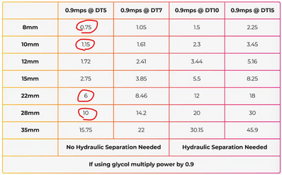
Having read many sources that suggest avoiding hydraulic separation if possible, and that it shouldn't be needed in most cases, I ended up looking into the theory myself. It's taken me a while to get to the point where I think I understand the chart on this Heat Geek page:
..Which I tried to use to analyse the situation with my property.
But I'd love to have someone check my logic! 😬
Our home:
- 4-bed property
- 2019 build, EPC high B (90)
- 151m2 floor area (if we include 2 voids in the attic eaves which buffer the room against external temp, as my EPC seems to have included)
- Very well insulated everywhere, very air tight (according to EPC test, just above the requirement for MVHR)
- UFH on whole ground floor, 6 rads + 2 towel rails between 1st & 2nd floors.
Estimated heat loss (at -2.1C):
Adlar - 6.9 kW
Octopus - 4.3 kW
Heat Punk - 3 kW (my own survey, done using U values from our EPC, and doing what I can to get the Total Annual Demand in kWh close to our actual current usage)
Actual energy use for heating and hot water for our gas boiler:
6700 kWh in 2024
The thing that's concerning the installer is the 10mm flexi plastic radiator tails.
Beyond that though, I can see 22mm copper from the boiler (on 1st floor), which is still 22mm copper on reaching the UFH manifold. And the UFH uses 15mm plastic.
Should we actually be worried?
Here's my thinking based on the Heat Geek sheet...
The primary pipework from HP will be 28mm.
According to the chart, with a 0.9 flow rate, at DT 5, a 28mm pipe can handle up to 10 kW of power.
That's absolutely fine with a total house demand of any of the above values.
Where the pipework splits to go up and downstairs, we have mostly 22mm copper.
22mm is fine for up to 6 kW power - But each pipe won't be supplying the full 6 kW from the heat pump anyway, since each one is supplying different floors and splitting off for the UFH etc.
From that 22mm, things like sinks, baths & showers are supplied by 15mm plastic. But that's HW - not relevant for space heating.
For individual rooms - each rad is supplied by 10mm plastic, which we should treat as if its 8mm copper due to plastic's narrower bore than copper.
According to the chart, 8mm can happily handle up to around 750 W of power.
The only room that could potentially get anywhere near that demand is the master bedroom on the 2nd floor. We have a range of heat losses calculated for that room:
Heat Punk - 586 W
Octopus - 731 W
Adlar - 1429 W
Both 586 and 731 are less than 750W. Adlar's own calcs seem very inaccurate, based on the estimated energy use being massively wrong (286% higher than our actual usage), so I hesitate to trust that 1429 is accurate.
The ground floor UFH pipes are 15mm plastic - treating that as 10mm copper, then each pipe can handle 1.15 kW. There are 3 UFH circuit pipes. The individual pipe supplying the largest area was designed for 1.17 kW demand and a slightly higher flow rate of 1, so that's within range too. According to Heat Punk and Octopus heat loss surveys, TWO 15mm pipes supply the open plan living/dining/kitchen room with a total heat demand of 968 - 1239 W, which I assume is fine since its shared between 2 pipes.
Hi. Welcome to the forum. I've used 15mm plastic to all my radiators and have calculated the correct power rates based on actual internal diameter of the plastic pipes.
I doubt you will have a problem getting enough heat to the radiators but is it the friction in the pipework they are worried about? If the pump cannot cope then you won't be able to get 0.9 mps.
Do you know what kind of inserts the pipes use? The metal ones have narrower profile and won't restrict flow as much but in reality I'm not sure how much of a difference it would make given they will only restrict over short distances.
Im not an installer so I might be talking complete b**ks but that's my understanding of the issues.
House-2 bed partial stone bungalow, 5kW Samsung Gen 6 ASHP (Self install)
6.9 kWp of PV
5kWh DC coupled battery
Blog: https://thegreeningofrosecottage.weebly.com/
Heatpump Stats: http://heatpumpmonitor.org/system/view?id=60
@bontwoody Thank you for the welcome, and reading my wall of text!
I doubt you will have a problem getting enough heat to the radiators but is it the friction in the pipework they are worried about? If the pump cannot cope then you won't be able to get 0.9 mps.
From my limited understanding, I believe that’s what the HG chart is helping determine. I’m not so concerned with rads being cold, rather that if we try to push too much water down a pipe that isn’t large enough, that will increase the flow rate higher than what is safe & sustainable for the pipe. Flow rates well above 1 (eg 1.5) are where you get resistance and friction issues, right? So by trying to ensure no individual pipe has to supply greater kW than is stated in the chart, the idea is we should be able to keep flow rates below 0.9 - 1 (the ideal flow rate range).
But maybe the HP won’t allow the flow rate to go damagingly high anyway, so that’s when we could get low flow issues instead? But I’m not sure it’s that smart.. 🤔
Do you know what kind of inserts the pipes use?
I don’t unfortunately, but that’s why I’m using the (hopefully worst case scenario?) rule of thumb of stepping down to the next smallest diameter when referencing the chart. ie Treating a 10mm plastic pipe as if it’s an 8mm copper - since the chart is based on copper pipes.
Oh I forgot to mention btw - The installer is planning on putting in a 6 kW heat pump which will only be supplying the heating! Hot water will be powered by a separate heat pump cylinder.
Posted by: @morganrOh I forgot to mention btw - The installer is planning on putting in a 6 kW heat pump which will only be supplying the heating! Hot water will be powered by a separate heat pump cylinder.
Interesting. Could you elaborate on why they're proposing doing this?
Get a copy of The Ultimate Guide to Heat Pumps
Subscribe and follow our YouTube channel!
@editor Their idea is that it improves efficiency due to the main heat pump not needing to ramp up the flow temp to meet hot water demands, and not needing to stop providing heat to the emitters while it does so (then needing to catch up after), so it makes the heating system much more "low and slow". And in summer the main HP can be switched off completely, just leaving the cylinder heat pump running. As a minor added benefit, the cold air exhaust from the cylinder can be routed (behind a controllable switch) to an internal room to provide a little bit of indirect cooling (only while the water is being heated) when desired - which is what we're planning to do. There's a few other theoretical efficiencies they claim from doing it like this too.
There's lots more info on their system here if you're curious:
And I'm interested to hear your thoughts on that concept!
Hi @morganr, welcome.
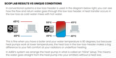
Interesting post. I looked at the Adlar literature. One thing jumps right out, this diagram, which is plain wrong. I need to call it out.
It shows 5degC loss on both the primary and secondary sides of a low loss header. For identical flows, where the primary and secondary sides are 'in balance', this defies the laws of thermodynamics and energy conservation. There's little or no detectible heat loss. The primary water inlet temperature will be almost the same as the secondary water outlet temperature, and the the secondary flow return will be almost the same as the primary return. There are slight thermodynamic losses due to the LLH, because of the static boundary layer between primary and secondary flow sides, and the casing of the low loss header vessel. They allow convection and conduction respectively. You've got the running costs of the secondary circulator, which will be more impactful than the energy efficiency loss of the LLH.
The diagram might be true if a plate heat exchanger was used to separate primary and secondary sides, because a plate heat exchanger causes quite noticeable efficiency losses. The primary side flow temperature has to be higher than the desired secondary side flow temperature. That's exactly what happens inside the heat pump - the condenser refrigerant vapour entering the plate heat exchanger has to be higher temperature than the primary water circuit flow temperature.
Whether you need a completely separate heat pump to supply your DHW is up to you. If you want your heating on constantly 24/7 at a set temperature it may be for you. However, most people set back overnight to a few degrees lower, during which time a DHW charge cycle can be programmed, perhaps to benefit from a lower tariff period, and while the house cools a little late evening. We charge DHW from 1pm-2:15pm each day using low tariff plus max diurnal outdoor air temperature, and the interruption to our wet radiator heating is about a 0.5degC drop in room temperature at worst. If your house is very well insulated and air-tight, you'll not even notice it.
@allyfish That does look wrong, doesn't it!
For identical flows, where the primary and secondary sides are 'in balance'
What about when that isn't the case, though? Considering IF they add a LLH to my system, it will specifically be to allow the HP side to run at a higher flow rate than the emitter side. Which I suppose will trigger the mixing they talk about in that screenshot, right? Also known as distortion, which impacts efficiency due to the HP having to run hotter?
If your house is very well insulated and air-tight, you'll not even notice it.
Yeah I do reckon the benefit of the HP pausing its heating task to switch to HW is unlikely to be noticeable in our house (and may even be beneficial).
But I think the second benefit will apply - I'm sizing radiators to aim for a 35 - 37°C flow temp, so a single HP having to suddenly go from 35 to heat water to 50ish is quite a big jump and would probably impact efficiency, right? Seems like it'd be happier being able to just chug along at 35 the whole time?
Ultimately, I don't think we NEED a separate HP for the water since 6kw alone should be more than adequate for both jobs (and I do plan on making use of our cheap night rate), but Adlar's system being "simpler" (so they say), with hardware straight from manufacturer, means their price is very appealing! 🤔 As long as it actually.. works.. I'll be happy!
@morganr my understanding of the HG table is that it indicates how much heat can be delivered through that pipe size at a flow 0.9 mps. This is the standard flow velocity used by installers. Above that you start to get problems like noise and pipe wear?
What I was trying to separate was the possibility that the pump that was to be used might not be able to achieve 0.9mps against the resistance to flow in your system and that was why they wanted to use the LLH.
Given the range of heat loss you have, your description of the house and the fact that it's not going to do the DHW, a 6kw heat pump sounds a bit on the large size to me. Can you sanity check it against previous usage readings.
House-2 bed partial stone bungalow, 5kW Samsung Gen 6 ASHP (Self install)
6.9 kWp of PV
5kWh DC coupled battery
Blog: https://thegreeningofrosecottage.weebly.com/
Heatpump Stats: http://heatpumpmonitor.org/system/view?id=60
@bontwoody Would the main consideration for determining whether the pump could achieve that flow (with the pipe resistance as it is) be the power capacity of the HP? ie if the HP is too small, it may not actually be able to achieve 0.9?
Since Adlar's own heat loss calc was 6.9 kW, could that be the reason for their concern? But in reality if our heat loss is much lower, as I suspect, then should 6kW be able to achieve 0.9 easily?
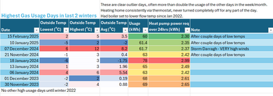
I agree that 6kW is likely to be oversized for us. I spent a long time on my own Heat Punk survey, used ProtonsForBreakfast's spreadsheets, and checked our gas usage on the coldest days of the last 2 years (highest usage day was 78kWh of gas = 3kWh from a HP if spread over 24 hours), and by all these metrics our heat loss is coming back at 4 kW or lower, which tallies up with our current annual gas usage (6700kWh).
But 6kW is unfortunately the smallest size that Adlar and Octopus do. And most other installers I've spoken to and have done heat loss surveys would still want to install 6kW units (or bigger! One said 12kW!) based on MCS guidance, and would charge us £2500 more for it. So unless we go very bespoke and convince an installer to give us a 5 kW, for about £4000 more than Adlar/Octopus are quoting, it seems we may need to compromise with an oversized unit..
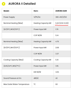
From what I can tell from this chart though (and I'm really not certain I'm reading this right, I find it quite confusing!), it seems like the Adlar unit (called Aurora II) is slightly underspec compared to the badged "6kW" anyway? But I'm not really sure how this compares to other 5-6 kW units out there?
@morganr Well you have certainly done due diligence 😁. I think its likely that your 4kw estimate is about right but a 6kw model shouldn't be grossly oversized so should be OK especially if the badged output is on the generous side.
The important metric really is it's minimum output.
The water pump power does not have to be linked to the size of the heat pump, although it may be true that bigger heat pumps have more powerful water pumps, i really dont know. My Samsung HP doesn't have an internal water pump so I can put any I fancy in the pipework so long as it reaches the magic 0.9 mps 😉
If your quote includes the LLH and you are happy with it. Perhaps it could be plumbed in such a way that it could be bypassed easily if you were unhappy with the COP and fancied trying it in a single loop.
I think Protons for Breakfast removed his but didn't think it helped much.
House-2 bed partial stone bungalow, 5kW Samsung Gen 6 ASHP (Self install)
6.9 kWp of PV
5kWh DC coupled battery
Blog: https://thegreeningofrosecottage.weebly.com/
Heatpump Stats: http://heatpumpmonitor.org/system/view?id=60
Well you have certainly done due diligence
I've certainly tried! 🤣 It's been mind-blowing how hard it is to convince some installers that their heat loss calcs MUST be wrong, though. That yes, we really are currently paying ~£500 a year for gas, not the £1500 they're estimating. Most find it very hard to believe! Which has been concerning me, that if we Don't get a pretty good SCOP, our bills could well increase after switching to elec..
If your quote includes the LLH and you are happy with it.
For the honor of having a LLH and secondary pump, they're quoting £175 extra. Which I'm happy to pay if it actually improves the system/stability of course. But.. not really happy to pay extra for a worse system, which the majority of the internet seems to be telling me it will be, if I let them add hydraulic separation. 😣
But am I right in thinking a LLH isn't as bad as a buffer tank..?
The important metric really is it's minimum output.
Do you think that "2.50" underlined in the chart is likely to be the HP's minimum output?
That's been my other concern actually.. that after doubling the size of some of our rads (they're currently all K1s), we might struggle to run the heating low enough. Some of those "coldest days" in the year are only just scraping 2.5 kWh required according to my math. What'll happen on the "medium" cold days? 🤔
- 26 Forums
- 2,406 Topics
- 54.6 K Posts
- 289 Online
- 6,092 Members
Join Us!
Worth Watching
Latest Posts
-
RE: Experience - New Build / Complete New Heating System
Your sap clculations should give you a heat loss figure...
By JohnnyB , 7 minutes ago
-
RE: Vaillant aroTherm not heating with many faults
@editor hmmm, our engineers Rae, Craig, Naz, Rob and Ry...
By ASHP-BOBBA , 51 minutes ago
-
RE: Post-Traumatic Heat Pump Stress Disorder
@editor Hi Mars. I totally agree with your comments. ...
By Richard24738 , 55 minutes ago
-
RE: Recommended home battery inverters + regulatory matters - help requested
Indeed! And my apologies, I should have expected you...
By Batpred , 1 hour ago
-
RE: I’m glad the cold spell is over!
@editor as a reply for this date the 6th of Jan in o...
By Nursethescreens , 2 hours ago
-
RE: Heat loss based on gas usage
@jamespa Thanks. The numbers posted above were jus...
By Bash , 3 hours ago
-
RE: Heat pump not reaching flow temperature
I would describe this as either a fault or a configurat...
By JamesPa , 3 hours ago
-
RE: Solis inverters S6-EH1P: pros and cons and battery options
@batpred I started reading this thread thinking I would...
By Hook , 5 hours ago
-
RE: Please help with the settings ecodan
@sheriff-fatman when I increase it to number 3, the ...
By nose1972 , 5 hours ago
-

RE: New Daikin 11kW Altherma 3M install - is it working as it should?
I forgot to mention: Octopus measured our heat loss at ...
By Toodles , 6 hours ago
-
RE: Considering MLCP (Multi-Layer Composite Pipe) for ASHP
Thanks Mars and thank you for reaching out to so many p...
By iotum , 7 hours ago
-
RE: Air source heat pump roll call – what heat pump brand and model do you have?
Forum Handle: @davec Manufacturer: Peak Energy Mode...
By DaveC , 7 hours ago
-
RE: Rate the quality of your heat pump design and installation
Well, the guy came out, turned the heat pump to max, we...
By razz , 7 hours ago
-
Midea R32 setup and bizarre running with lengthy off periods?
Hi I am new to the world of ASHP and have just had a re...
By Countryman Helmsley , 7 hours ago
-
RE: Setback savings - fact or fiction?
Given the weather has been relatively stable, the empir...
By Batpred , 7 hours ago
-
RE: GSHP WOES! Midland based engineer recommendations?
@editor That is very kind! Thank you so much.
By johnbroome , 9 hours ago
-

RE: ASHP Energy Consumption: Aira 12kW heat pump
@wally Hi I am not sure how large your house is b...
By TechnoGeek , 10 hours ago
-
RE: Predicted Heat Loss & Needs from MCS calcs vs EPC vs actual
I've been thinking along similar lines to @tim441 from ...
By Sheriff Fatman , 10 hours ago
-

Thanks, @technogeek. Good to hear about the accuracy. ...
By Majordennisbloodnok , 11 hours ago
-
RE: Advice for a novice on Mitsubishi Ecodan 6kW
In my case it was a very specific pattern of behaviour ...
By Sheriff Fatman , 11 hours ago

