I'm leaving aside the message from your electrician for the moment.
But it is useful, and I'll return to it anon.
I've been reading the Installation Instructions for the Growatt MINxx00-TL-XH series and the matching ARK-XH battery series.
Astonishingly there is no single connection diagram for the wires connecting these units.
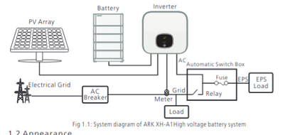
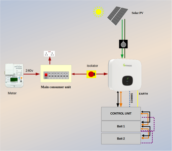
The best that Growatt provides is the generic diagram showing where the inverter and battery system fit within the overall electricity supply for the house:
Only by reading through each section of the Installation Instructions do we learn what is actually involved in that single black line which runs between the inverter and battery.
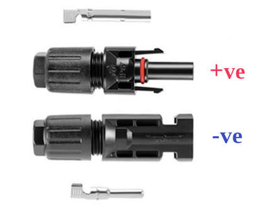
Moreover, Growatt decided to use exactly the same type of connector for both the solar-panels and the +ve & -ve battery wires!
These are 'standard' MC4 connectors, but there were better choices for the battery terminals.
[sigh!]
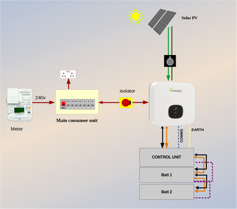
Here's my own connection diagram, based on what I've combined from the two Growatt manuals:
Before explaining anything further, can you give me a rough idea of your ability to use basic tools?
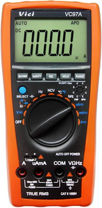
Do you have a multimeter?
Do you have the plastic MC4 connector tool, which looks like this?
The MC4 tool is needed to disconnect the battery from the inverter.
There are sprung-lugs on either side of the connector which need pressing simultaneously.
Save energy... recycle electrons!
Posted by: @transparentn you give me a rough idea of your ability to use basic tools?
Do you have a multimeter?
Do you have the plastic MC4 connector tool, which looks like this?
Thanks @transparent I currently don't have these tools but I will purchase them.
I will update the thread after the electrician's visit, that should happen shortly.
Cheers
E
You don't need a multimeter of any great accuracy.
I'd suggest keeping below £30, made in China:
I have a couple of auto-ranging Vici multimeters which I use when working with inverters and batteries
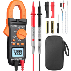
But a Clamp Meter like this one badged Proster, would be more useful because you can measure DC current running through a battery wire
without needing to disconnect anything.
Please ask here if you need help
Save energy... recycle electrons!
Thanks.
The electrician stopped by and verified with the clamp meter that there is no power deducted from inverter to battery system.
There is also no lights display within battery unit. Now, as the battery is in warranty (10 years) I asked Growatt to find a solution asap (either them or Cahill).
The electrician also said that when the company installed the RCBO the regulation did not yet require bi-directional mode (it only came into effect in 2024 apparently...). So this is something I may need doing.
The electrician said that what he was doing with the inverter on (checking the battery fuse) was indeed (as I suspected) dangerous, so I am glad I did not venture myself.
@eliuccio Sometimes changes in electrical regs only apply to new installation but will often also apply if any modifications are carried out on an existing installation; they require compliance with the current version of the regs. Regards, Toodles.
Toodles, heats his home with cold draughts and cooks food with magnets.
Posted by: @eliuccioThe electrician stopped by and verified with the clamp meter that there is no power deducted from inverter to battery system.
I think we could've all guessed that from your descriptions thus far!
But that doesn't necessarily indicate a fault in either the inverter or battery.
If the inverter has sent a software command to the battery, for example, which tells it to 'Stop', then no current will flow either way.
The key issue at the moment is whether there is any voltage on the battery connections to the inverter.
Depending on whether the Growatt ARK design puts the batteries in series or parallel, I would expect to see 52v or 104v DC.
Posted by: @eliuccioThe electrician said that what he was doing with the inverter on (checking the battery fuse) was indeed (as I suspected) dangerous,
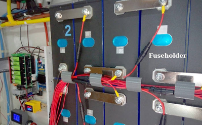
Hmm. I would've needed to see where that fuse was, and what bare connections were exposed in order to agree with it being dangerous.
The LiFePO4 battery types you have are not inherently dangerous.
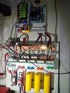
All of my connections are exposed and can be touched without the possibility of electric shock:
The main 'danger' is that someone drops a metal tool across the connections.
That will momentarily produce an arc-flash, but the BMS system in your Growatt units would then 'open' to prevent current continuing to flow.
When you look at the Growatt ARK datasheet, which you posted earlier, you will see that each battery module limits current to a maximum 41A.
Posted by: @eliuccioThere is also no lights display within battery unit. Now, as the battery is in warranty (10 years) I asked Growatt to find a solution asap (either them or Cahill).
On the balance of probabilities, I would agree with you that the battery system is more likely to be at fault than the inverter.
But having no lights visible might also occur if
- a cable connection had come loose or been corroded
- a fuse or trip inside the inverter had opened to isolate the battery
Posted by: @eliuccioThe electrician also said that when the company installed the RCBO the regulation did not yet require bi-directional mode (it only came into effect in 2024 apparently...). So this is something I may need doing.
That's true.
BEAMA issued a safety notice in March 2024, and the IET published an amendment to the electricians' accreditation organisations a couple of months later.
But the risks were actually identified before August'23 because that's the date on the first document I found when researching the issue.
It just takes the official governance organisations that long to act.
We should remember that solar inverters have been installed in houses for decades.
The UK Government's Feed-In Tariff subsidies started in April 2010.
Many of those early sites will have been installed with only a basic MCB which gives no protection against fire or electric shock.
As time went on, solar installers will have used RCBOs, none of which would've been bi-directional because they weren't manufactured until late '23.
The vast majority of those houses won't catch fire due to electrical faults,
and the majority of those home-owners also won't die as a result of an electric shock from an inverter which has gone faulty.
Your electrician is correct to say that it's your responsibility to pay for a bi-directional 32A RCBO to replace the existing one.
Note what I wrote earlier in this thread:
Posted by: @transparentUs moderators here, such as myself and @majordennisbloodnok are approaching such issues from an understanding of the background physics.
That's different to an electrician.
They comply with regulations... simply ensuring that each wire gets connected to the right position.
That's great when everything is working fine, but not when there's a relatively massive fault to be handled!
Electricians and solar installers obey regulations. Full stop.
They are under no legal obligation to write to past customers and warn them.
But here on the forum we do try to alert owners of solar installations prior to March'24 of the dangers.
We don't have to... but I feel there's an ethical responsibility to do so.
I also talk directly to engineers and organisations who write the regulations.
Again, I believe there's an ethical reason for doing so.
For example, I feel it is unacceptable that there is no mandatory symbol, visible to end users, which identifies a bi-directional trip.
Proteus have recently introduced one on their bi-directional RCBOs,
but that's part of their own branding, rather than being universally agreed.
It's very rare for electricians and installers to get involved in such discussions.
Save energy... recycle electrons!
When dealing with a fault, electricians have a responsibility to make the caller aware of potential risks.
I doubt the regulation stops the electrician fixing the fault unless everything is made to comply to current regs.
Having said all this, some of the risks associated with lack of bidirectional RCD/RCBOs can catch even experienced electricians, so I would get it replaced. If one of same size and ratings to the one installed is available, it can be a very simple job. But once you look to match the exact specs needed, this can be tricky. So this is not always a simple job. My inverter is an 8k hybrid and for this rating, this is not so simple.
16kWh Seplos Fogstar battery; 8kW Solis S6-EH1P8K-L-PLUS hybrid inverter; Ohme Home Pro EV charger; 100Amp head, HA lab on mini PC
The batteries would be in parallel, not series.
if one of them had a fault, it would be detected by the charging circuit in the Inverter and shutdown.
if possible, disconnect both batteries and re connect one at a time, check status on inverter screen to see if it thinks a battery is now connected, then ask inverter to report charge level of each battery.
Does anyone know whats inside the battery, is it just a dumb bank of cells and a temperature sensor, or is there a charge control module?
As the battery gets full, its resistance to being charged goes up, this is detected by the charger which will slow down the charge rate after 90% to protect the battery, and then cease charge at 99%
I'm sorry @batpred - I'm finding it difficult to follow what you're saying here.
1: In this case no electrician has alerted @eliuccio regarding the type of RCBO.
The electrician who attended on site has made a comment about a 'danger' of accessing/checking/changing a battery fuse,
but we don't know what fuse that comment refers to. There is no fuse mentioned in the technical manual for the ARK battery.
2: Your second sentence is a double negative.
Are you saying that an electrician can or cannot fix a 'fault' on a battery without also changing the type of RCBO which supplies the inverter?
3a: You wrote: "some of the risks associated with lack of bidirectional RCD/RCBOs can catch even experienced electricians, so I would get it replaced."
I don't follow your logic here. I've just made precisely the opposite point.
Whether or not an electrician understands the risks isn't relevant because electricians will simply implement the regulations.
The need to replace the existing uni-directional RCBO is unaffected by whatever level of understanding an electrician has concerning the technology.
3b: You wrote: "But once you look to match the exact specs needed, this can be tricky. So this is not always a simple job. My inverter is an 8k hybrid and for this rating, this is not so simple."
Why?
Please explain why the specification makes it tricky to replace the uni-directional RCBO in the case of your 8kW hybrid inverter.
What warning are you giving to other readers who might also have an 8kW hybrid unit?
And why?
It is important that advice given on this forum is accurate and can be substantiated.
This is more-so the case when it is a safety issue.
Please state your sources.
Save energy... recycle electrons!
Posted by: @agentgeorgeThe batteries would be in parallel, not series.
That might indeed be the case, and there are diagrams in the installation manual which suggest that.
However, Growatt themselves have marketed this ARK system as "High Voltage".
That's what they say the "H" means in the product number.
Until anyone here can explain why that is so, I think we must err on the side of caution.
High-voltage LiFePO4 battery assemblies are increasingly common.
For example, the 2nd generation GivEnergy systems fall into this category.
Posted by: @agentgeorgeif one of them had a fault, it would be detected by the charging circuit in the Inverter and shutdown.
[...]
is it just a dumb bank of cells and a temperature sensor, or is there a charge control module?
It is most certainly not just a bunch of dumb cells.
The largest enclosure in the ARK system is indeed a Control Unit.
See this diagram which I posted earlier:
We have no idea what functionalities are divided between
- the Growatt TL-XH inverter
- the 'Control Unit'
- the individual battery modules
Could others posting here please also check the full technical manuals for the TL-XH Inverter and the ARK Battery System.
I've spent hours poring over these before posting here, and I'd appreciate it if others could confirm or oppose my observations by referring to the documents.
I'm wary of being the only one who is cross-referencing source material.
Save energy... recycle electrons!
I enquired to my installer to add a second battery. I was told they add it on top of the current battery pack. The second battery has a plate on the bottom which is removed and slots ontop of the first battery. A coms cable is connected between the 2 packs
The time quoted for the job was up to 2h, as they had to allow both batteries to get to within 0.5v of each other
This 0.5v is stated in the instructions you linked to.
These instructions are assuming you have done the task before and are not a step by step guide to adding extra batteries.
last time I enquired, the cost of a 5kW pack had dropped to £1800.
- 26 Forums
- 2,396 Topics
- 54.3 K Posts
- 367 Online
- 6,077 Members
Join Us!
Worth Watching
Latest Posts
-
RE: Recommended home battery inverters + regulatory matters - help requested
To me that makes sense. Bond the inverter neutral to t...
By JamesPa , 2 minutes ago
-

RE: Power outages and storms: A surprisingly good DNO experience
To be fair, the interactions I’ve been having recently ...
By Majordennisbloodnok , 25 minutes ago
-

RE: Setback savings - fact or fiction?
As far as I am aware, the majority, if not all, of the ...
By cathodeRay , 2 hours ago
-
RE: Advice for a novice on Mitsubishi Ecodan 6kW
Fair point. The highest frequency of defrosts I'd seen...
By Sheriff Fatman , 13 hours ago
-

RE: Heatpunk Floor plan issues
It's usually the complete opposite... seldom that Safar...
By Mars , 13 hours ago
-
RE: RDSAP10 effect on existing heat pump EPC rating?
@mike-patrick interesting update - thanks.I've been thr...
By Tim441 , 14 hours ago
-

RE: Fan is clipping ice build up from the front of unit.
@majordennisbloodnok I’ll not go there thanks! Toodles.
By Toodles , 16 hours ago
-

RE: Running from backup generaor in powercut?
@majordennisbloodnok Back in the 80’ or 90’ we had a te...
By Toodles , 16 hours ago
-
RE: Running my new Nibe ASHP efficiently
I'm new to the forum. Did you get a reply to this last ...
By Mike @ Camelot , 17 hours ago
-

RE: ASHP Energy Consumption: Aira 12kW heat pump
@grantmethestrength MCS requirements for DHW capacity h...
By Toodles , 18 hours ago
-
RE: New Mitsubishi Ecodan 11.2kW installation - L9 errors and maybe more
Great to hear! I just figured this out a day or tw...
By anotherdaveuk , 19 hours ago
-
RE: Help me keep the faith with my air source heat pump installation
@adamk I'm observing my own system at low temperatures ...
By dr_dongle , 1 day ago
-

RE: Free Ecoheat Heat Pump Install
@deltona Yes older houses are problematic like that, bu...
By bontwoody , 2 days ago
-
RE: Radiator sizing sanity check
As I mentioned early on the cost of supplying and fitti...
By JamesPa , 2 days ago
-
RE: Electricity price predictions
Great point, one of the key ones in my chat with Octopu...
By Batpred , 2 days ago
-

RE: New Fogstar 15.5kWh upright solution
Let me point out that there are many Chinese suppliers ...
By Transparent , 3 days ago
-

RE: Weather compensation- why you should use it
@majordennisbloodnok — The Two Ronnies Mastermind sketc...
By cathodeRay , 3 days ago
-
Just realised that this image of the cylinder cupboard ...
By Sheriff Fatman , 3 days ago
-

RE: Rodents! A word of warning for heat pump owners
Two thoughts: 1: Let's ask @david-s if Primary Pro in...
By Transparent , 3 days ago

