Posted by: @transparentActive balancers don't operate at the kilohertz range.
Their micro-controller takes time to measure the cell voltages and decide which is the highest and lowest in the set.
To do so it first switches off the current flow on all balance leads.
(Sorry if this comes across as picky; I felt people might find this video interesting)
Stuart Pittaway's analysis of a (somewhat broken) active balancer reveals an interesting design that does not involve cell voltage measurement.
I'll have to think a bit about the balancing method.
I'm not familiar with the Active-Balancer you're using.
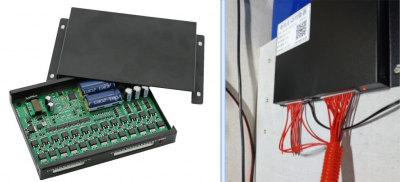
The ones I have here are the larger/newer version, albeit from the same manufacturer Jikong/Neey
As you can see, the strategy is quite different.
My version has just two large capacitors and a ladder network of mosFET switches to connect them across the separate cells.
Save energy... recycle electrons!
The spec of the one I have is 100mOhms, and I can read on it the cap values it uses - they are 3x 6.3V 2200uF per channel. The total charge transferred per period will then be:
Q=C.(V2-V1) = C.DV where DV=DeltaV, voltage between a pair of cells (say in a 2 cell system)
Q = Iav.t, where the time in question is 1/f, where f is the operating frequency . Appreciate I will not be flat, but we don't care about that, we just want the average not the actual waveshape.
so Iav = C.DV.f
As R=DV/Iav then:
R = 1/C.f)
or f = 1/(R.C)
So in this case, C=6.6mF, R = 0.1Ohms, so the calculated f = 1/(0.1*6.6E-3) = 1.5kHz
I hadn't worked this out before, but there's going to be a compromise between component cost (capacitance cost is significant) and static power loss (which will increase with operating frequency) for a given output impedance going on, so it was an informed guess.
Maybe I'll measure it - but not while it's connected to a massive battery in case my probe slips 🙂
As for the polyfuse - they're only there to protect the wires in the event the active balancer pcb is completely toast. They can do that - in fact I just tried one with a weedy bit of wire across an old car battery, and it just tripped straight away, the thin bit of wire didn't even feel hot. Maybe there's some other fault condition, but I think this covers the most worrying - pcb/mosfet short circuit otherwise making the copper wire 100s of C, smoking PVC insulation, horribleness.
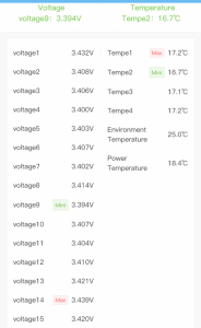
Our battery is almost charged now - It's had 2A continuously for 4 days, so about 200Ah going into each cell. Now they are fuller, discrepancies are showing as the cells are at the steep end of their voltage:SOC curve:
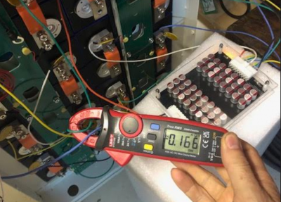
Cell 14 is the highest voltage, 45mV above the lowest, cell 9. I have a dc clamp on meter, that can measure down 1mA dc - it does drift off by 10mA over a few minutes, but can be reset. Clamping onto the bms wires left and right of a cell will show the bms current overall to the cell - note the wires go through the clamp in different directions, we want to find Icellpositive - Icellnegative. If the clamp fitted on the busbar it would be simpler - then I'd measure every cell current directly.
Cell 14 has 166mA being removed from it by the bms
Cell 9 has 140mA being added to it by the bms
That's a 306mA difference in charge current between the two cells that have a 45mV discrepancy, or 45mV/306mA = 147mOhms, which matches well with the expected BMS resistance.
I intend to leave it like this for "a while", see how well they pull together while I figure out what to do with the inverter.
In the end it took 5 days to charge at 2A, so about 250Ah went into each cell. When the cells are charged, any variation appears, and it took another 12 hours for the variation in cell voltages to reduce - down to 3.496 to 3.498V as measured by the Seplos controller. So I took off the extra balancer, and tightened all the bolts up with a torque wrench. There’s some pvc tape wrapped around the torque wrench - don’t want any nasty shorting surprises!
or anyone.
Hi I have been looking everywhere for information such as this to help me work through the G99 fast track application, my understanding is the 8kw has to be submitted under the G99 rules but can be fast tracked as compliant and also as G100 feed limited also falls under advice and notify criteria rather than apply for permission, but that bits not as important as asking if anyone can help me with tips re the following.
So, working through this I see it was some time ago that you @transparent did this application, I have a Sunsynk eco 8k both G98 and G99 compliant and has all the registration required and wondered if you remember what you entered in key sections of the form.
With the National grid application form I obviously submit the relevant compliance details and line plans however in the section and i quote
"Details of Export Limitation Scheme
Where an export limitation scheme is required by SGI-2 or SGI-3 please
state export limit setting in amps."
form link below,
Q1
I assume i enter 16amps? although as we know the inverter can produce 32Amps but is limited by export settings as required under G100 🙂 ?
Q2
The other question is as I have 30kw of storage although as required under the fast track system its managed by the inverter and therefore compliant how does this effect my application.
Q3
As i have 20 potential KW of solar dc power the max for the unit at 8800w do i show this on my diagrams?
Sorry to be so dumb I just dont wish to apply and find i got it all wrong.
Q4.
DO i have to do the additional limitation form they reference.
If it was not for the uK weather id be tempted to be off grid avoiding all of this but its not viable in our climate.
Any advice on the form sections completion appreciated.
Relevant form.
Many thanks in advance,
Skipster.
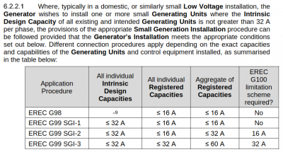
Here's a section from the G99 specification which is available from the ENA website,
The Sunsynk 8k inverter has inbuilt current limiting to 16A (3.68kW) and therefore falls within SKI-2.
Posted by: @skippyI have 30kw of storage although as required under the fast track system its managed by the inverter and therefore compliant how does this effect my application.
As i have 20 potential KW of solar dc power the max for the unit at 8800w do i show this on my diagrams?
You can show these figures, but they're irrelevant to the G99 application process.
G99 is only assessing the amount that can be exported to the grid.
What capacity of solar panels and battery storage you have, will make no difference.
Remember that the form is being read by a human with common sense.
Once you've stated the model number of the Sunsynk inverter, they'll be able to see on the ENA database what current limitation is inbuilt.
Save energy... recycle electrons!
Thanks.
That confirmed my thoughts and appreciated
Application and documents sent and will report back when I hear something.
New member here - looking for some help on this subject. I'm installing a Seplos Mason battery and need to select a suitable G98 certified inverter/charger to use. I will not be installing PV so a hybrid inverter is overkill for this application.
I was hoping to use the Solis unit noted at the start of this thread but it doesn't appear to be certified. What is everyone else using with their battery only systems ?
(Just to make things more complex I live in Northern Ireland which further reduces my options, potentially to zero)
Hi @alphonsox - you're welcome here, whether you use Irish electrons or British ones.
Why do your options equate to zero potential?
1: If you're not going to be generating electricity within your property (solar or otherwise), then can we assume that you won't be wanting to export back to the grid?
And if that's the case, then you don't have to buy an inverter certified to G98.
The EREC G-standards apply to sites which supply the grid.
You would still require a G98 inverter if it was to be supplying your home in parallel with the grid,
but not, for example, if it were used to run a heat-pump in an "off-grid" configuration.
2: And if Assumption-1 is true, then can we also assume that your storage battery is for electricity to be used within the house?
If so, then there are two possible reasons for installing a battery:
a. You will use a Time-of-Use (ToU) tariff to charge the battery when electricity is cheaper
b. You want to have electricity when there is a power-cut
... or both.
For the moment feel free to stick with non-technical explanations of what you'd like to achieve.
We can fill in the kWh and £s later on.
Save energy... recycle electrons!
@transparent Thanks for the quick response.
This is a pure money saving exercise exploiting ToU. The house is currently running on E7 and I want to minimise my peak consumption by charging the battery overnight and discharging during the day. I don't have an issue with power-cuts here so I expect to use a grid coupled solution with no islanding required. My expectation is that the battery would supply the first 16A of load with the grid only being called on if the house load exceeds this. Clearly no export is needed or desired.
OK. Understood. So you will require a G98 certified inverter because it's grid-tied.
And you'll want one with a Current Transformer (CT) which is configured to prevent all export.
Whatever is stored in the battery will only get used within your house.
Have you considered a SunSynk 'Bi-directional' inverter?
They are designed to permit no export to the grid by default.
Moreover that export-limitation mechanism already has approval by the ENA (Electrical Networks Association).
So you could opt for an inverter model with greater output than 16A, and still be granted approval from your DNO (which in your case is NIEN).
You can verify this by applying online for G99F/T (Fast Track) permission, and stating a particular SunSynk model.
G99 applies to combined storage and export, and is explained more fully on that website.
You don't then have to install that model. You can change your mind and apply again.
But at least that will give you an idea of any 'issues' which the DNO thinks might apply to your particular site.
Save energy... recycle electrons!
- 27 Forums
- 2,495 Topics
- 57.8 K Posts
- 397 Online
- 6,220 Members
Join Us!
Worth Watching
Latest Posts
-
RE: What determines the SOC of a battery?
@batpred I didn't write the Seplos BMS software, I a...
By Bash , 24 minutes ago
-

RE: Electricity price predictions
Sorry to derail this thread ‘slightly?’ but back to the...
By Toodles , 33 minutes ago
-

RE: Humidity, or lack thereof... is my heat pump making rooms drier?
Without knowing it, @andrewj, you've laid down the gaun...
By Majordennisbloodnok , 52 minutes ago
-
RE: Testing new controls/monitoring for Midea Clone ASHP
@tasos and @cathoderay thanks. I have some history grap...
By benson , 57 minutes ago
-

I am having my existing heat pump changed to a Vaillant...
By trebor12345 , 1 hour ago
-
Our Experience installing a heat pump into a Grade 2 Listed stone house
First want to thank everybody who has contributed to th...
By Travellingwave , 2 hours ago
-
RE: Setback savings - fact or fiction?
@cathoderay The input power is largely determined by...
By RobS , 3 hours ago
-

RE: Solis inverters S6-EH1P: pros and cons and battery options
Just to wrap this up here for future readers: The S...
By Batpred , 5 hours ago
-
RE: Struggling to get CoP above 3 with 6 kw Ecodan ASHP
Welcome to the forums.I assume that you're getting the ...
By Sheriff Fatman , 5 hours ago
-
RE: Say hello and introduce yourself
@editor @kev1964-irl This discussion might be best had ...
By GC61 , 6 hours ago
-

@painter26 — as @jamespa says, it's for filling and re-...
By cathodeRay , 10 hours ago
-

RE: Oversized 10.5kW Grant Aerona Heat Pump on Microbore Pipes and Undersized Rads
@uknick TBH if I were taking the floor up ...
By JamesPa , 21 hours ago
-

RE: Getting ready for export with a BESS
I would have not got it if it was that tight
By Batpred , 23 hours ago
-
RE: Need help maximising COP of 3.5kW Valiant Aerotherm heat pump
@judith thanks Judith. Confirmation appreciated. The ...
By DavidB , 1 day ago
-

RE: Recommended home battery inverters + regulatory matters - help requested
That makes sense. I thought better to comment in this t...
By Batpred , 1 day ago
-
Bosch CS5800i 7kW replacing Greenstar Junior 28i
My heat pump journey began a couple of years ago when I...
By Slartibartfast , 1 day ago
-

RE: How to control DHW with Honeywell EvoHome on Trianco ActiveAir 5 kW ASHP
The last photo is defrost for sure (or cooling, but pre...
By JamesPa , 1 day ago
-

RE: Plug and play solar. Thoughts?
Essentially, this just needed legislation. In Germany t...
By Batpred , 1 day ago
-
RE: A Smarter Smart Controller from Homely?
@toodles Intentional opening of any warranty “can of wo...
By Papahuhu , 1 day ago
-
RE: Safety update; RCBOs supplying inverters or storage batteries
Thanks @transparent Thankyou for your advic...
By Bash , 1 day ago
-
RE: Air source heat pump roll call – what heat pump brand and model do you have?
Forum Handle: Odd_LionManufacturer: SamsungModel: Samsu...
By Odd_Lion , 1 day ago
-
RE: Configuring third party dongle for Ecodan local control
Well, it was mentioned before in the early pos...
By F1p , 2 days ago
-

RE: DIY solar upgrade - Considering adding more panels
I know this is a bit old, but it made me wonder what co...
By Batpred , 2 days ago


