I have a tn-c-s earthing arrangement - is that PME? A brief Google leads me to think it is. I do have an earth wire emerging from the service fuse.
The Zappi is connected to my consumer unit via a 6mm SWA cable so I assume it has an earth connection back to the consumer unit which itself is connected ultimately to the earth from the service fuse. I'll take a picture tonight.
Other chargers also have this PEN fault detection such as the hypervolt.
Yes, TN-C-S is what we call PME, but is more descriptive for those with a technical understanding.
Your substation transformer and any poles carrying overhead wires should have a PME label fixed to them.
Posted by: @gunboatdiplomatOther chargers also have this PEN fault detection such as the hypervolt.
That's ok for now,
but the standards which apply in May 2024 might not be the same when you next need to summon an EV Charger installer.
Standards change as we gain more experience:
a: When OVO first started fitting V2G chargers for their trial four years ago they encountered problems with protection trips getting hot.
Their resolution was to buy-in a special 'box' from a UK company which measured the current differently and would cause the trips to open their contacts under a wider range of fault conditions.
But within months, those boxes too were deemed unsuitable.
Instead, OVO's engineers had to revisit test sites and install Type-B double-pole RCDs at £250 each.
That's what we mainly use today.
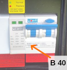
You can see the B40 label on the Proteus RCD photo which @howerpiece uploaded earlier today
b: Tens of thousands of houses in UK will have solar panel inverters connected to the grid via an RCBO.
Those have been installed for over 20-years.
But it was only within the last six months that BEAMA sent out a warning that many of those will no longer operate if there's any earth leakage.
Ie there's no longer protection against fire or electric shock. 😲
The IET is about to issue an urgent Amendment to the Wiring Regulations to address this.
Electricians will now need to fit bi-directional RCDs, followed by a separate MCB.
My own consumer unit was upgraded to that arrangement just yesterday!
I've issued a Warning on this issue here on the forum, which you can read... and then preferably tell everyone you know who might be affected.
Save energy... recycle electrons!
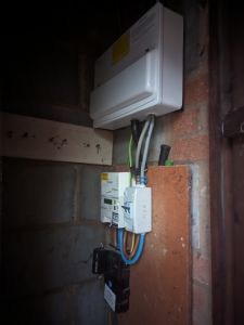
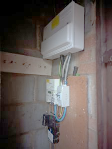
So another service cut out and meter for you @transparent:
Bit of an awkward space to try and get it all in one shot.
My EV charger is on my main consumer unit a 32A RCBO, not a 40A RCBO (the Zappi manual specifies 32A is fine). The RCBO is a 2 pole 32A B curve type A (not a type B!).
From the Zappi manual:
- Built-in 30mA Type A RCD + 6mA DC RCD protection (EN 62955)
- Built-in protection against the loss of the protective neutral and earth (PEN) conductor as required by BS
7671:2018 Amendment 1:2020(The “Wiring Regulations”)
I am guessing the 6mA DC protection is the equivalent of what a type B RCD would provide.
When I next summon an EV installer I expect they will tell me everything has been wrong as it will be someone different person - unfortunately the local electrician who fitted it and the new consumer unit is no longer local and has shut up shop.
The bit about bidirectional RCDs is interesting as I do hope to get solar and that was one of the reasons I went for a Zappi. A good bit of information to put in front of any installers I end up getting a quote from.
Let me just turn the light on in that cupboard @gunboatdiplomat
Ah... that's better.
So this is a very straightforward distribution board with the house earth derived from the right side of the Service Fuse.
Ie it's a PME supply.
Yes, a 32A RCBO to supply the Zappi is ok.
The current rating of a trip is dictated by the cable connected to it, not just the device at the end!
That Zappi spec Built-in 30mA Type A RCD + 6mA DC RCD protection isn't equivalent to a Type-B RCD.
Type B is required when the connected appliance(s) aren't certified to have less than 6mA of DC component in the leakage current.
If Zappi have designed their charger such that DC leakage current is below 6mA, and it's certified as such, then a Type A is satisfactory.
This level of technical detail is normally only encountered on forums run by electricians!
The plethora of new low-carbon technology is such that few electricians and heat-pump installers are able to keep up-to-date with everything.
MCS and RECC aren't helping because they create specifications which are overly legalistic and lack background explanations.
Simply being able to assign blame for some infraction is of little benefit either to the professionals or us consumers.
I'd like us to move towards a system which is informative and encourages good practice.
This forum is an example of how that might work.
Save energy... recycle electrons!
Posted by: @transparentPerhaps @editor can help to direct a Zappi user with technical knowledge to respond here please?
I've not been around this week so catching up on posts. I'll contact the folks at Zappi (myenergi) for comment.
Get a copy of The Ultimate Guide to Heat Pumps
Subscribe and follow our YouTube channel!
@transparent hope I’m where I should be now
do you run the solar batteries down to zero, I take them to 20%, and up to 100%. I discharge to grid during the premium time on octopus and presently a mostly charged battery. During winter the battery is done because of the ashp by 11am or sooner but as you know it’s been worked on so might be better. Only got 2.5 kwp solar but working on installer to take me up to 4kwp since I had so much problems with them and my installations. And I forked out 384 quid for an engineer because they said it was ok and it wasn’t.
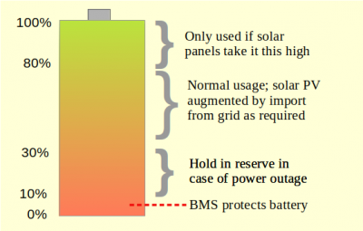
@david999 I have 14kWh of battery capacity, I initially limited it to 85% charge and 15% discharge as to minimise 'wear'. I think this is sensible for most people, 90% / 10% would also seem reasonable if lack of capacity is an issue. Battery degradation is most likely to occur at very low and very high states of charge.
However, I've since altered my settings to 85% charge and 0% discharge (the BMS prevents it from actually hitting 0%). I often only use 6-10kWh of electricity a day so it rarely goes below my previous minimum, but on heavy use days I get the full benefit of the battery. And if it discharges down to (near) 0% once a month is that going to drastically affect its degradation? Probably not, thinks I.
Note that many battery products have buffers to overcharging and undercharging built in, so each product specification must be considered in isolation. E.g. a 5kWh battery might actually be 6kWh, but the software only allows you to access 5kWh of it - in which case 0% discharge and 100% charge would be completely appropriate.
Yes, this an appropriate topic @david999 🤗
Running batteries to the limits in either direction isn't a good idea.
Most users with storage batteries will be operating a charge/discharge cycle between 30%-80%
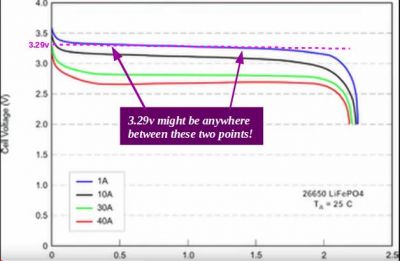
In practice this is fairly easy to achieve because storage batteries tend to use Lithium Ferrous Phosphate (LiFePO4) chemistry, which has greater voltage variations the closer you get to it being 'full' or 'empty'
In the middle of the State-of-Charge (SoC) curve it's very difficult to tell what capacity is available because the voltage is almost flat.
For that reason professional SoC measurement devices tend to employ 'coulomb-counting'.
They use a shunt to measure current on the way in and on the way out again.
Couple that with a measurement of cell-voltage, subtract the internal losses, and you can derive a reasonable approximation of the charge (in coulombs).
The Battery Management System (BMS) should be configured to prevent charging above 3.6v per cell, or below 2.94v.
Your inverter is 'inset' from those limits.
It might be configured to charge a 16-cell battery between 47.5v - 57v for example.
If everything operates as it should, then the BMS won't have to intervene.
So why have a BMS at all?
... because the cells in a battery won't accept charge evenly.
Unlike an inverter, which is only concerned with the overall battery voltage, the BMS has a sense-wire to each individual cell.
If one cell in the pack reaches 3.6v, the sum of all 16-cells in series might still be below the 57v level which the inverter is looking for.
The BMS must intervene to protect that one cell from being overcharged.
Can you actually fully discharge a cell?
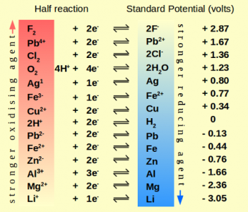
Taking us back to the heady days of GCSE Science, you might be vaguely aware of the electro-chemical series.
You will have seen a chart which lists metals (and a few non-metals), and assigns a potential difference (voltage) to each.
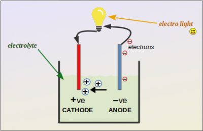
If you take a pair of metals from the list, you can build a battery by placing them in an electrolyte.
That allows +ve ions to travel towards one metal (the cathode), and the electrons which have been stripped away, to pass along the wires from the anode.
So long as you have the two metals and the electrolyte, there must be a voltage at the terminals where the wires can be connected.
... and if that is so, then how could you possibly 'run a battery down to zero'?
To achieve zero charge in the battery, then you must surely have caused damage.
What damage that is will depend on the chemistry of the battery.
It might be that the cathode has become coated with 'salt' ions and is no longer in contact with the electrolyte.
Or perhaps the electrolyte has been 'boiled away' as a cloud of vapour!?
And that takes me to the recently published PAS63100 standard from BSI which is designed to prevent fire and other battery faults from destroying your home:
Just what does this mean?
Suppose I have a Lithium-ion battery with LiMNC chemistry, which has a nominal 3.6v across the terminals.
If the manufacturer recommends that it not be discharged below 2.94v does that make it any more 'safe' than if it was at 3.1v?
LiMNC cells are the ones often seen on videos when an electric-scooter or hoverboard bursts into flames.
That can occur in-use due to mechanical damage.
Fire breaks out because the battery chemistry creates an exothermic reaction when the internal plates touch each other.
As it burns, it gives out yet more heat.
That has little to do with its 'state of charge'.
It's not inherently safer if the cells had only 2.94v across the terminals, because it can still catch fire.
Or suppose I had a cell of LiFePO4 chemistry, and I discharged it down to 2.7v.
Does that equate to a 'flat battery'?
If I connected a piece of copper wire to each terminal and brought the ends together, would they no longer create an arc and 'weld themselves' together?
PAS63100 is suggesting a strategy which doesn't actually provide the level of safety which Annex-A implies.
All batteries should be treated as if they are 'live'...
and especially those used in Electricity Storage systems, which can pass high-currents due to their low internal resistance.
Only when we appreciate that fact, will we be able to work safely in their vicinity.
Save energy... recycle electrons!
@transparent very interesting reading and loving it. You touch on saving battery in reserve for an outage, mine has an EPS facility but the installer refuses to wire it in although the plug is in the kit. Is this a difficult function to wire in myself, currently even with batteries I can’t power the house during an outage. Or so I’m told.
Posted by: @david999very interesting reading and loving it.
and I think that's the point.
The easiest way to make progress towards Net Zero is for the general public to enjoy the journey.
It's not that we should learn the laws of science in order to achieve a 'Pass', but that we 'get it' in the same way that we might appreciate a joke.
I'm old enough that I learned chemistry and physics in an era when dropping glowing splints into gas jars of Ethane, Ethylene and Acetylene was still permitted.
I have acquired a fundamental understanding of how much energy is contained in a triple-bond.
The concept impacted me in no less a fashion than the wooden stool above the jar of acetylene being introduced to the lab ceiling.
Both impacts have lasted decades.
Posted by: @david999... mine has an EPS facility but the installer refuses to wire it in although the plug is in the kit.
That's not easy to answer without knowing the manufacturer and model of battery 🤔
A photo of the battery and the plug would be equally useful!
Save energy... recycle electrons!
@transparent It’s a growatt hybrid inverter and the plug goes directly into the bottom of it. I’m led to believe I need something at the consumer unit that cuts off grid and takes the power from the batteries through the inverter.
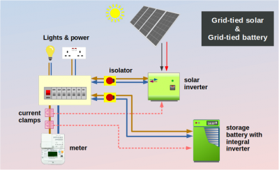
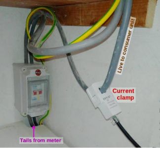
The device which plugs into the underside is almost certainly a current clamp.
It goes around the live supply between the meter and the consumer unit.
The current clamp allows software within the inverter to limit export to the grid... or possibly prevent it altogether (zero export).
Adding separate battery storage can complicate the issue...
especially if the solar inverter and the one within the storage battery don't 'know' about each other.
You need G99 approval from your DNO because there are two devices with grid export capability.
It's possible that the combination you wish to install is not listed on the ENA database, resulting in the DNO declining the G99 application.
That's one reason why a professional installer would (rightly) refuse to connect a current clamp.
I struggled with just such an 'unrecognised' pairing for 2 years, whilst taking part in a trial of Battery Storage being undertaken by OVO.
It wasn't efficient, and could only understand the concept of storing all possible solar-generation in the battery first.
On sunny days it would then be limited to 16A grid-export, whilst discarding excess generation above that threshold.
I would advise no one else to proceed down that route.
Save energy... recycle electrons!
- 27 Forums
- 2,495 Topics
- 57.8 K Posts
- 397 Online
- 6,220 Members
Join Us!
Worth Watching
Latest Posts
-
RE: What determines the SOC of a battery?
@batpred I didn't write the Seplos BMS software, I a...
By Bash , 24 minutes ago
-

RE: Electricity price predictions
Sorry to derail this thread ‘slightly?’ but back to the...
By Toodles , 33 minutes ago
-

RE: Humidity, or lack thereof... is my heat pump making rooms drier?
Without knowing it, @andrewj, you've laid down the gaun...
By Majordennisbloodnok , 52 minutes ago
-
RE: Testing new controls/monitoring for Midea Clone ASHP
@tasos and @cathoderay thanks. I have some history grap...
By benson , 56 minutes ago
-

I am having my existing heat pump changed to a Vaillant...
By trebor12345 , 1 hour ago
-
Our Experience installing a heat pump into a Grade 2 Listed stone house
First want to thank everybody who has contributed to th...
By Travellingwave , 2 hours ago
-
RE: Setback savings - fact or fiction?
@cathoderay The input power is largely determined by...
By RobS , 3 hours ago
-

RE: Solis inverters S6-EH1P: pros and cons and battery options
Just to wrap this up here for future readers: The S...
By Batpred , 5 hours ago
-
RE: Struggling to get CoP above 3 with 6 kw Ecodan ASHP
Welcome to the forums.I assume that you're getting the ...
By Sheriff Fatman , 5 hours ago
-
RE: Say hello and introduce yourself
@editor @kev1964-irl This discussion might be best had ...
By GC61 , 6 hours ago
-

@painter26 — as @jamespa says, it's for filling and re-...
By cathodeRay , 10 hours ago
-

RE: Oversized 10.5kW Grant Aerona Heat Pump on Microbore Pipes and Undersized Rads
@uknick TBH if I were taking the floor up ...
By JamesPa , 21 hours ago
-

RE: Getting ready for export with a BESS
I would have not got it if it was that tight
By Batpred , 23 hours ago
-
RE: Need help maximising COP of 3.5kW Valiant Aerotherm heat pump
@judith thanks Judith. Confirmation appreciated. The ...
By DavidB , 1 day ago
-

RE: Recommended home battery inverters + regulatory matters - help requested
That makes sense. I thought better to comment in this t...
By Batpred , 1 day ago
-
Bosch CS5800i 7kW replacing Greenstar Junior 28i
My heat pump journey began a couple of years ago when I...
By Slartibartfast , 1 day ago
-

RE: How to control DHW with Honeywell EvoHome on Trianco ActiveAir 5 kW ASHP
The last photo is defrost for sure (or cooling, but pre...
By JamesPa , 1 day ago
-

RE: Plug and play solar. Thoughts?
Essentially, this just needed legislation. In Germany t...
By Batpred , 1 day ago
-
RE: A Smarter Smart Controller from Homely?
@toodles Intentional opening of any warranty “can of wo...
By Papahuhu , 1 day ago
-
RE: Safety update; RCBOs supplying inverters or storage batteries
Thanks @transparent Thankyou for your advic...
By Bash , 1 day ago
-
RE: Air source heat pump roll call – what heat pump brand and model do you have?
Forum Handle: Odd_LionManufacturer: SamsungModel: Samsu...
By Odd_Lion , 1 day ago
-
RE: Configuring third party dongle for Ecodan local control
Well, it was mentioned before in the early pos...
By F1p , 2 days ago
-

RE: DIY solar upgrade - Considering adding more panels
I know this is a bit old, but it made me wonder what co...
By Batpred , 2 days ago

