Safety update; RCBOs supplying inverters or storage batteries
BEAMA have issued a safety update (March 2024) regarding the use of RCBOs to connect PV inverters or storage batteries.
This is not yet part of the IET Electrical Wiring Regulations, but it is sufficiently serious that an amendment is being expedited.
Overview: household electrical circuits are wired from a Consumer Unit which contains a number of trips.
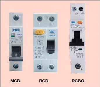
Most trips are there to prevent excessive current being passed through wires/cables. Those are MCBs (Miniature Circuit Breakers).
It is common for a consumer unit to have one or more RCDs (Residual Current Detectors).
These compare the outgoing current on the Live wire, with that being returned on the Neutral.
If there is an imbalance, the contacts will open to prevent fire or electric shock to someone who has touched a live cable.
Increasingly, electricians are fitting RCBOs for individual power circuits.
These combine the functions of an MCB and RCD.
They will open the contacts either for over-current, or because current is leaking away somewhere.
If a single-circuit RCBO trips out, then at least the lights remain on so you can see what's gone wrong!
RCDs and RCBOs both have a test button.
This should be pressed periodically to check that it will open the contacts to protect against electric shock
When solar panels or storage batteries are installed, it is not mandatory that the circuit is supplied from an RCBO. An MCB is sufficient.
However, many installers do use an RCBO to provide an extra level of safety for when it might be necessary for an inverter to undergo maintenance.
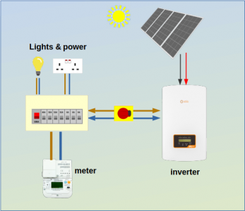
Most Solar Inverters and Storage Batteries are "Grid tied".
They export to the mains supply through the same wires which connect them to the consumer unit.
A grid-tied inverter will have a G98 certificate, and requires permission from the regional DNO to install it.
This common arrangement means that electricity will pass through the RCBO in either direction.
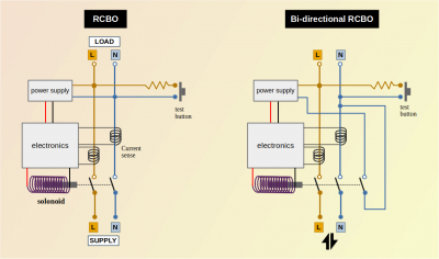
The RCBO contains a small amount of electronics to handle the current sensing.
When there is a fault (either over-current or earth-leakage) a solonoid is energised (switched on), which opens the contacts.
If the RCBO was on a normal power circuit, opening the contacts would remove power from the electronics.
The trip would remain open until the lever was manually moved, and the solonoid would no longer be powered-on.
But if there is power still being applied in the reverse direction by an inverter or storage battery, when the contacts open, the solonoid remains energised.
Such a small solonoid will overheat and burn out.
The circuit can still be re-powered using the lever, but it will no longer be able to protect against electric shock.
The home owner won't know that.
The solution is to use a an RCBO specifically designed for bi-directional use.
A bi-directional RCBO has a third pair of contacts.
When the solonoid operates to open the trip, that 3rd contact set removes power from the electronics, and the solonoid coil is de-energised, preventing burn-out.
How can you tell if an RCBO is bi-directional?
Most RCBOs have arrows to show the direction of current, or have a label which denotes Supply and Load terminals.
A Bi-directional RCBO will not be marked for Supply and Load.
It may also have a set of arrows pointing in both directions.
If an RCBO isn't marked as being bi-directional, then it isn't.
The IET Wiring Regulations aren't retrospective.
When the amendment is released which specifies the need for a bi-directional RCBO, there will still be many thousands of installations which appear to have an operational RCBO, but it will only offer protection against over-current. It won't be acting to prevent fire or avoid electric shock.
It is up to forum members here to spread the word to others and advise that an existing RCBO is exchanged (by an electrician!) for a bi-directional type.
Save energy... recycle electrons!
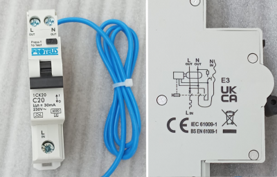
This photo shows a bi-directional RCBO by Proteus at Redditch.
The symbols are correct, and the third-contact which the solonoid switches is visible in the diagram on the side.
What I still don't like is:
- the terminals being labelled 'In' and 'Out'
- no bi-directional symbol or marking on the part of the RCBO which remains visible to the householder after installation is completed
This particular RCBO is Type A
and Curve C... which defines the time it takes to trip due to over-current.
Most household MCBs and RCBOs are curve-B, which operates faster.
I use Curve-C trips to supply circuits which are likely to have large inductances connected (motors in a workshop or an inverter).
Update 28may24:
I have a response from Proteus Switchgear to say that they are already acting on the BEAMA directive and "will remove the in/out and also add on a bidirectional arrow symbol to the front of compliant devices"
The changes will filter through once existing stocks have been exhausted.
Save energy... recycle electrons!
- 26 Forums
- 2,396 Topics
- 54.3 K Posts
- 370 Online
- 6,077 Members
Join Us!
Worth Watching
Latest Posts
-
RE: Recommended home battery inverters + regulatory matters - help requested
Thanks all for the help, this seems to be nearly as com...
By JamesPa , 5 minutes ago
-
RE: Advice for a novice on Mitsubishi Ecodan 6kW
I hadn't spotted that there were two pumps in the UFH (...
By JamesPa , 25 minutes ago
-
RE: Setback savings - fact or fiction?
Never assume it makes an ass of u and me! You need the...
By JamesPa , 29 minutes ago
-
RE: New Mitsubishi Ecodan 11.2kW installation - L9 errors and maybe more
Before I answer your specific questions just one more t...
By JamesPa , 40 minutes ago
-
RE: Help me keep the faith with my air source heat pump installation
@agentgeorge Fortunately the one thing that you *won't*...
By dr_dongle , 43 minutes ago
-
RE: ASHP Energy Consumption: Aira 12kW heat pump
@chandykris Thank you for your detailed response.It is ...
By Wally , 2 hours ago
-
RE: Electricity price predictions
Great point, one of the key ones in my chat with Octopu...
By Batpred , 11 hours ago
-
RE: Running from backup generaor in powercut?
Definitely and professionals sometimes miss it. I had...
By Batpred , 11 hours ago
-

RE: New Fogstar 15.5kWh upright solution
Let me point out that there are many Chinese suppliers ...
By Transparent , 16 hours ago
-

RE: Weather compensation- why you should use it
@majordennisbloodnok — The Two Ronnies Mastermind sketc...
By cathodeRay , 16 hours ago
-
Just realised that this image of the cylinder cupboard ...
By Sheriff Fatman , 20 hours ago
-

RE: Rodents! A word of warning for heat pump owners
Two thoughts: 1: Let's ask @david-s if Primary Pro in...
By Transparent , 20 hours ago
-
RE: Solis S6-EH1P8K-L-PLUS – Why I Chose It and What I’ve Learned So Far
In the diagram below, I describe my understanding of th...
By Batpred , 20 hours ago
-
I need to have a look out for it. I know IBM feeds some...
By Batpred , 21 hours ago
-
-
RE: Daikin Atherma ASHP Cycling 6 Times an Hour?
Thanks for your reply. Yes that's a good idea to try a...
By John Marshall , 1 day ago
-

RE: Hot water heating in parallel with space heating
An external heat exchanger would need a pump which woul...
By bontwoody , 1 day ago
-
RE: Gen 6 Samsung ASHP losing 20C of DHW in 60 min directly after generation
@ecobaker Thanks for this. I've had it in both slots. ...
By andbeck , 2 days ago
-

RE: Air source heat pump circuit not operational
Welcome to the forums. If the thermostat shows it’s c...
By Mars , 2 days ago

