How To Balance Radiators & the Role of the Lockshield Valve: A Homeowner's Guide
Posted by: @alfapat@jamespa Thanks , looks like I should remove it then . Question I have , if the HP pipes are 28mm and they are directly connected to the smaller CH pipes , does that not cause a problem , except if you had control of the pump speeds ?
If you remove the buffer you will also need to remove the secondary pump.
Re your concern, it depends. Some further detail will help determine.
- What capacity is your heat pump/house loss?
- do the 22mm CH pipes split (eg upstairs/downstairs) or is there only one 22mm feed?
- Do you know what your rad side DT is when its cold?
4kW peak of solar PV since 2011; EV and a 1930s house which has been partially renovated to improve its efficiency. 7kW Vaillant heat pump.
Posted by: @alfapat@jamespa Thanks , looks like I should remove it then . Question I have , if the HP pipes are 28mm and they are directly connected to the smaller CH pipes , does that not cause a problem , except if you had control of the pump speeds ?
If you remove the buffer you will also need to remove the secondary pump.
Re your concern, it depends. Some further detail will help determine.
- What capacity is your heat pump/house loss?
- do the 22mm CH pipes split (eg upstairs/downstairs) or is there only one 22mm feed?
- Do you know what your rad side DT is when its cold?
OK James,
Ill see if I can answer your questions. the heat pump is 16kh , would the loss be on the commissioning ? The original commission had another HP alongside 9kw., but this was removed when another company accepted to take over the whole thing when the original installers were liquidated. So I only have there proposal.
System is placed in a large loft and CH pipes travel down to one floor , they start plastic but down to copper .
DT?
OK.
16kW is not compatible with 22mm pipework, and barely compatible with 28mm at a typical design DT across the radiators of 5C https://www.heatgeek.com/does-my-pipework-need-upgrading-for-a-heat-pump-with-cheat-sheet/
That said 16kW may well be an overestimate (or even a gross overestimate) of your requirement. Its quite plausible that this to be the case - over sizing is common even now and back when yours was installed probably endemic. Two relatively recent 'professional' 3hr surveys for my house came out at 16kW, its actually 7kW or possibly a bit less.
Essentially, to omit the buffer tank and second pump, you need to satisfy the conditions that
with your existing pipework (or pipework you can reasonably replace)
- sufficient heat is transferred through the pipework (at DT across the rads of ~5) - essentially a mass flow calculation knowing the heat loss of your house, which you may not currently know
- the heat pump wont complain about flow rate - down to the heat pump spec
- the flow rate isnt too high causing excess noise or erosion of pipework - can be assessed once the above is known
- the primary pump has sufficient oomph (probably it does, but needs to be checked)
I think the summary is, this needs a study that is more in depth than that which I can realistically do on this forum. Essentially it needs a partial re-design of your system but wherever possible using the same components. A randomly picked heat pump installer is unlikely to be capable of that (because they would be too reliant on 'rules'), maybe a 'heat geek' qualified one might. Its also possible that a commercial heating designer might because they should be used to actually doing calculations (some aren't, as I discovered to my cost in a work-related project).. Alternatively you need someone who can do the analysis 'from first principles'. Its not fundamentally difficult, but it needs a visit and some thinking which is not entirely 'in the box'.
Unless you are prepared either to do this yourself or to pay someone to do this, you are probably stuck with the buffer.
There is one more option, which is that you plumb switchable bypasses (ideally such that the buffer becomes a 2 port volumiser) and 'suck it and see'. If you fancied a couple of days of plumbing in the summer season that would be good prep for next year!
Otherwise its a case of living with a 10-15% penalty doe to the buffer, which may or may not be necessary unless you are prepared to replumb your central heating system.
Im sorry to be the bringer of bad news, maybe others have an alternative suggestion.
4kW peak of solar PV since 2011; EV and a 1930s house which has been partially renovated to improve its efficiency. 7kW Vaillant heat pump.
This is depressing , I have spent now a couple of months now trying to sort out a solution or some sort of headway on this forum to readdress the biggest investment (apart from buying the house) and sorting this Air source running cost.
I feel absolutely useless as what to do now apart from trying something like Homely.
I have now spent £25000 on a heating system that simply is pants! To put very lightly.
If you were willing to supply more info I could probably give you a good idea if just scrapping the buffer will work.
- How old is the installation (2015?)
- What make and model of heat pump (9kW + 16kW Samsung Monoblock - two pumps?)
- How are the two pumps connected/controlled?
- What was the assessed heat loss of the building 13.5kW?
- Diagram of heating pipes (including diameters/materials and rough lengths) from where they exit/enter the buffer, ideally until they first divide (including diameters of the divided pipework)? Would it be practical to swap the pipework up to the first divide?
- Gas consumption prior to heat pump installation?
- Floor area and construction of house?
- Temperature difference between flow to radiators and flow from radiators when its cold, OAT at that time and how long it had been cold for (eg overnight, a day)?
- Can you hear the water in the pipework?
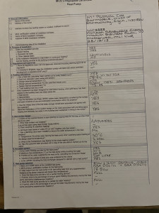
Some of this is in the certificate you posted above. and where it is I have pasted in the values for you to check I understand correctly. If you could advise the rest, or at least most of it, I can give you some more pointers
With 13kW demand (If thats real - which it may not be) I really cant see how a single 22mm primary feed to/from rads will work at the typical 5C deltaT that heat pumps operate at. So if that is what the demand is, and if there is really only a single 22mm feed, then the buffer is a necessary element of the design to allow the secondary to operate at a larger delta T flow -> return to the primary. But if this is the case then you should measure this on your thermometers which so far I haven't seen.
More detail may help point you in the right direction or, if you are lucky, confirm that 13.5kW is a gross overestimate and you can in fact get away with 22mm.
4kW peak of solar PV since 2011; EV and a 1930s house which has been partially renovated to improve its efficiency. 7kW Vaillant heat pump.
Sorry about rant last night.Posted by: @jamespaIf you were willing to supply more info I could probably give you a good idea if just scrapping the buffer will work.
- How old is the installation (2015?)
- What make and model of heat pump (9kW + 16kW Samsung Monoblock - two pumps?)
- How are the two pumps connected/controlled?
- What was the assessed heat loss of the building 13.5kW?
- Diagram of heating pipes (including diameters/materials and rough lengths) from where they exit/enter the buffer, ideally until they first divide (including diameters of the divided pipework)? Would it be practical to swap the pipework up to the first divide?
- Gas consumption prior to heat pump installation?
- Floor area and construction of house?
- Temperature difference between flow to radiators and flow from radiators when its cold, OAT at that time and how long it had been cold for (eg overnight, a day)?
- Can you hear the water in the pipework?
Some of this is in the certificate you posted above. and where it is I have pasted in the values for you to check I understand correctly. If you could advise the rest, or at least most of it, I can give you some more pointers
With 13kW demand (If thats real - which it may not be) I really cant see how a single 22mm primary feed to/from rads will work at the typical 5C deltaT that heat pumps operate at. So if that is what the demand is, and if there is really only a single 22mm feed, then the buffer is a necessary element of the design to allow the secondary to operate at a larger delta T flow -> return to the primary. But if this is the case then you should measure this on your thermometers which so far I haven't seen.
More detail may help point you in the right direction or, if you are lucky, confirm that 13.5kW is a gross overestimate and you can in fact get away with 22mm.
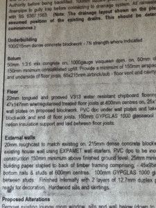
Insulation increased before installation to Loft at 300mm. Insulation below floor 2022 170mm
Installation 2015
one pump 16kw , the other sold after recommisioning. Sub section 4.1 (v1) on THE MCS Certificate shown above is Heat Loss 13.48kw
Distance from Buffer to eaves in loft approx. 3m then a drop to outside ground 2.70m.
Timber buit House on Dwarf wall . Insulaation on outer interrnal room wallsapprox 1inch polystyrene silver backed stuff!
Total area 199sq m
28mm hp piping to split joint between DHW and Buffer joints 30mm
Oil burner before with Wood stove on zone valves (amature set up) Unknown running cost as only moved in 2015
Pics to follow easier on phone
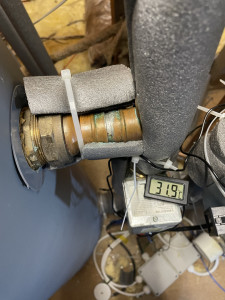
transfer.System temps shown passive no circ required.
and layout to eaves.
I am told that TRV ‘s would be installed along with buffer and controlled by Danfoss thermostat shown earlier in threads. As the TRV’s are fully open now and the system changed using lock shields
With your insulation upgrades its quite possible that you may be able to dispense with the buffer without changing the pipework. Can you clarify the following (which I cant work out from your photos).
- Diagram of heating pipes (including diameters/materials and rough lengths) from where they exit/enter the buffer until where they first divide (including diameters of the divided pipework). By divide I dont mean divide between CH and DHW, I mean divide into different feeds to the CH emitters. Would it be practical to swap the pipework up to the first divide?
- Temperature difference between flow to radiators and flow from radiators when its cold and the heating is working. OAT at that time and how long it had been cold for (eg overnight, a day)?
- Can you hear the water in the pipework?
4kW peak of solar PV since 2011; EV and a 1930s house which has been partially renovated to improve its efficiency. 7kW Vaillant heat pump.
Posted by: @jamespaWith your insulation upgrades its quite possible that you may be able to dispense with the buffer without changing the pipework. Can you clarify the following (which I cant work out from your photos).
- Diagram of heating pipes (including diameters/materials and rough lengths) from where they exit/enter the buffer until where they first divide (including diameters of the divided pipework). By divide I dont mean divide between CH and DHW, I mean divide into different feeds to the CH emitters. Would it be practical to swap the pipework up to the first divide?
- Temperature difference between flow to radiators and flow from radiators when its cold and the heating is working. OAT at that time and how long it had been cold for (eg overnight, a day)?
- Can you hear the water in the pipework?
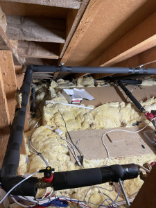
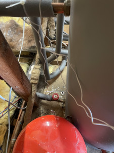
The picture attached shows the Ch pipes top and bottom, (never mind the expansion vessel that is scrap ) the pies come out and in about 15” in copper 22mm then take a right turn in 22mm plastic for 9 feet another turn for a couple of feet into copper 28mm and drop down from the loft and under the floor. I think all rads are on 15mm . I’ll get temp at evening and record flow and return and Oat At present late afternoon 11c , flow temps 27c and 39 out CH Controller says house 21.4 , 9.6 outside temp, circ 39.7, DHW 48.5.
So heating pipes go from 22 copper to 22 plastic to 28 copper? What a lazy sod of a plumber who fitted the heat pump
Would it be practical to replace the 22mm with 28. If so there is a high probability it will work without buffer and secondary. Better still keep buffer repurposed as a 2 port volumiser.
It might work without upgrading the pipework, but no real way to tell other than trying it. Personally I would be tempted just to plumb a switchable bypass to the buffer tank and secondary pump and see what happens. Given the plastic push fit connectors (see earlier comment about plumber) that might not be so difficult.
4kW peak of solar PV since 2011; EV and a 1930s house which has been partially renovated to improve its efficiency. 7kW Vaillant heat pump.
Update
Midnight
Samsung Controller readings are House temp 22.3 outside -0.3 33.4 rising as bath run , water 23.5 .
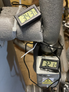
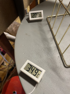
Readings in Loft Flow out to CH 37.9c back in 24.4c From Hp 42.8 Return to Hp just before zone valves changed to DHW Replenish as bath run 34.9c Hope that helps !
Oh weather Station says -1.3 Indoor 22.9c to 23.3c indoors
Posted by: @alfapatUpdate
Midnight
Samsung Controller readings are House temp 22.3 outside -0.3 33.4 rising as bath run , water 23.5 .
Readings in Loft Flow out to CH 37.9c back in 24.4c From Hp 42.8 Return to Hp just before zone valves changed to DHW Replenish as bath run 34.9c Hope that helps !
Oh weather Station says -1.3 Indoor 22.9c to 23.3c indoors
Sorry thats lots of numbers, but no clear explanation what they are measuring.
What is needed is the temperatures of flow to and return from the radiators (ie the deltaT across the radiators) when its cold outside and the central heating only is working.
Why - because if its much greater than 5C it indicates that the secondary is running at a higher deltaT than you would normally run a heat pump at, which may indicate that flow in the secondary will be a problem if you remove the buffer. On the other hand if you previously turned down the speed of the secondary pump it may just be down to this so if you did previously turn down the speed of the secondary pump please say so (with the figures) or turn it back up again for the experiment.
Attached sketches of switchable bypasses for the secondary pump and buffer tank. When pump is bypassed it also needs to be turned off. What you need to determine is, with the secondary pump/buffer out of the loop, do you get sufficient flow. If you do you are good to go, if you dont then there is a problem which may or may not be solved by swapping out the lengths of 22mm. The flow requirement for the heat pump will be given in the manual and the heat pump itself will almost certainly measure and report it somewhere in the UI and also complain if it is insufficient.
4kW peak of solar PV since 2011; EV and a 1930s house which has been partially renovated to improve its efficiency. 7kW Vaillant heat pump.
- 26 Forums
- 2,396 Topics
- 54.3 K Posts
- 405 Online
- 6,077 Members
Join Us!
Worth Watching
Latest Posts
-
RE: Advice for a novice on Mitsubishi Ecodan 6kW
In my case it was a very specific pattern of behaviour ...
By Sheriff Fatman , 7 minutes ago
-
RE: Vaillant aroTherm not heating with many faults
@ashp-bobba Yeah I'll give it a go, will check filter...
By Anon67 , 16 minutes ago
-

@majordennisbloodnok it has been a few weeks since addi...
By TechnoGeek , 17 minutes ago
-

RE: RDSAP10 effect on existing heat pump EPC rating?
@transparent Perhaps the names at the end of the docume...
By Toodles , 28 minutes ago
-
RE: Predicted Heat Loss & Needs from MCS calcs vs EPC vs actual
COP of 3 perhaps a little low and you say that you don'...
By benson , 60 minutes ago
-
RE: Heatpunk Floor plan issues
@jamiejones85 A2A they will design on dynamic heat loss...
By ASHP-BOBBA , 1 hour ago
-
RE: Considering MLCP (Multi-Layer Composite Pipe) for ASHP
I think the concern was about crud being forced from th...
By iotum , 1 hour ago
-

RE: Recommended home battery inverters + regulatory matters - help requested
The usual type of underground cable with a metal 'outer...
By Transparent , 1 hour ago
-
RE: Rate the quality of your heat pump design and installation
Welcome to the forum and I am sorry you are disappointe...
By JamesPa , 1 hour ago
-
RE: Fan unit Making terrible noise HELP!!
can you post a video looking inside, at and through the...
By ASHP-BOBBA , 2 hours ago
-

RE: Setback savings - fact or fiction?
Excellent graphics and description Rob…. But to my mind...
By SUNandAIR , 3 hours ago
-
RE: Heat pump not reaching flow temperature
@davec Ive had a look at the screenshots. Lots of th...
By JamesPa , 14 hours ago
-

RE: Power outages and storms: A surprisingly good DNO experience
Agreed, which is no more nor less than a customer shoul...
By Majordennisbloodnok , 19 hours ago
-

RE: Running from backup generaor in powercut?
@batpred In our case, 3 times each day when the Octopus...
By Toodles , 19 hours ago
-
RE: New Fogstar 15.5kWh upright solution
@batpred Here's the latest Fogstar ready built pack....
By Bash , 21 hours ago
-
RE: Solis inverters S6-EH1P: pros and cons and battery options
Solis confirmed that the S6 works with a single battery...
By Batpred , 22 hours ago
-
RE: Who has a V2G EV installation
I am wondering if in any V2X, would the car battery eve...
By Batpred , 23 hours ago
-
RE: New Mitsubishi Ecodan 11.2kW installation - L9 errors and maybe more
OK. I think your system, which seems well designed, is...
By JamesPa , 1 day ago
-

RE: Fan is clipping ice build up from the front of unit.
@majordennisbloodnok I’ll not go there thanks! Toodles.
By Toodles , 2 days ago

