PV inverters seem to interact
Posted by: @geo3geoI'm going to replace the consumer unit I need to take a step back and plan properly to sort out/make provision for, these other issues at the same time.
Yes, absolutely.
Cut out a set of paper scraps, each 18mm wide.
Label them with MCB, RCD, RCBO etc.
And start shuffling them around on a larger piece of paper which represents the (new) Consumer Unit, and the secondary enclosure I suggested for your PV inverters.
You can then label the larger sheet with the circuit names.
Some Consumer Units have the Main Switch at left, and some at the right.
Others allow you to choose which end you want it.
Next to the main switch, leave two module spaces for a pair of Transient Suppressors.
After those, the other trips are generally arranged with the largest current ones first.
So your lighting circuits (6A) are at the far end.
It took me several weeks to plan my layout... which now extends to three enclosures, each 21-modules wide, stacked vertically above each other!
My overriding requirement was for future flexibility.
Save energy... recycle electrons!
Wed 14th Feb, garden MCB closed, garden inverter isolator open. earth tripped between 4:45am and 4:50am. EV on program charge from 0:30 to 05:30. EV charge recorder says it was on for 4hrs !?!?
As the post content is expanding sideways, crossing topic boundries, I wonder if this discussion would be better continued outside the forum (?)
I'd recommend we leave this discussion here @geo3geo
The underlying causes of RCDs tripping isn't at all clear.
We are both experiencing the same problem, but with quite different designs of inverter.
To add to the knowledge-base, we need others to come across this topic and contribute their own insights.
I'm deliberately keeping my explanations simple because we want this discussion to be read by those without engineering experience and degrees.
Here's my present overview:
- I have three inverters with internal transformers, whilst you have two inverters which use (solid-state) electronics to create the sine-wave output.
- You have an old RCD, which will be Type-A, whilst I have an RCBO.
- In both cases we are seeing the trip contacts open on a device which detects imbalance between the current going out on the 'live' and that returning on the 'neutral'.
- We have got a third-party report of similar tripping on my type of inverter with internal transformers.
That's too little information to reach a conclusion at this stage.
Transients:
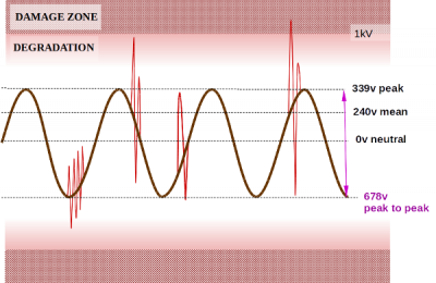
These are understood to be voltage anomalies which can be caused from external sources such as lightning, or internal sources such as an electric motor switching off (back-EMF).
For a single-phase domestic supply, that means the spike/surge is outside the 678v peak-to-peak voltage of a mains feed at 240v AC:
To cause sufficient current imbalance that a 30mA-rated RCD trips-out there would need to be considerable energy within those transient spikes.
But it's possible.
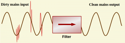
Lower-energy transients from an internal source can be removed by inserting a spike filter into the supply.
These are commonly available because they are usually installed in mains-operated medical equipment.
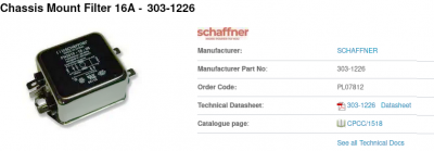
I have one within the isolation-switch for my TIG welder, but facing the opposite way around. It prevents spikes from the welder being propagated to other equipment in that workshop ring-main. It's rated 16A and costs £19 from CPC-Farnell
I could place such a filter on the supply to each of my inverters to see if that affected spurious tripping.
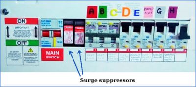
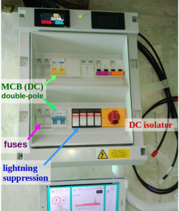
I also have a pair of Surge Suppressors within my consumer unit, directly after the Main Switch.
They serve two functions:
- any externally-induced spike will be quenched at the point of entry to the house
- any appliance generating a spike within the house may damage other devices on that circuit, but the Suppressors will quench that over-voltage transient before it could be passed to other circuits.
As I've used such Surge Suppressors for 30+ years, I tend to buy from the high-end of the market.
The leaders in this technology are Phoenix Contact, based in the German Black Forest.
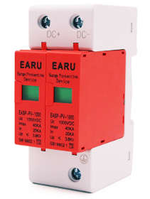
The pair in the above photo will successfully handle lightning-strikes up to 40kA.
They self-heal between the lightning transients.
Surge Suppressors are now commonly fitted within new consumer units.
These are usually devices manufactured in the Far East, and can cost as little as £20/pair
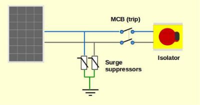
There are also specialist anti-surge devices which can be fitted on the pair of down-leads from rooftop solar panels.
As I have four separate solar-panel arrays on my rooftop, and the house is on a hill, PV lightning suppressors are an 'essential'.
Once again, I use Phoenix Contact units, costing around £100 per array.
Having said that, I can't see how a solar-panel surge arrestor would have any affect on the RCD which supplies mains power to the inverter.
Spike filters and surge suppressors need to be installed with a good earth connection.
When energy from a surge is removed from the live or neutral, it's the earth wire which carries the charge away.
Save energy... recycle electrons!
@transparent Yes I agree, let's leave it here for now. This morning's 5am trip has really thrown a spanner in the works, I thought I'd really pinned down the conditions that cause a trip. Everything was so repeatable. I'll now have to do more days of monitoring to see what pattern transpires. In the meantime I'll order a surge suppressor or two. I'll post something when I have something solid to add.
In the meantime I would like to say a really big thank you for all the crystal clear information you've put up here on this problem.
Signing out for now, Geo
After over a month since the last post on this topic I can now report that it's all been resolved. I've done a blog on it all which can be read at duellinginverters.blogspot.com - just click here
Well that's a relief in one sense @geo3geo in that you now have 2 operational inverters, but without the mains trip opening.
The less-than-welcome news is that it was achieved by installing a firmware upgrade from the manufacturer, Solis.
We don't know what they've changed!
At one point in your blog, I'd wondered if we might be heading in the direction of an Raspberry-Pi-controlled robotic arm to detect sunrise and throw a towel over the shed PV array!
That would, of course, have been an ARM-powered solution 😉
Your experience also raises another slightly-worrying aspect of grid-tied inverters...
... the manufacturers seem to be aware of 'aberations' which they inflict onto the grid of sufficient magnitude that they can cause a trip to open.
That begs the question of how/why the ENA is approving such devices under G99.
I can understand them being assigned G98 certification because that's an in-house test against a written specification.
But G99 applies when there is more than one export-device on site and the potential to export above 16A per phase.
That means the ENA has investigated the situation and placed the export-capable devices on their approved list.
I'm currently working on the design of devices which are 'grid-friendly' in a variety of different ways.
So I don't like the sound of there being thousands of devices already installed which are possibly:
- causing earth-loop currents
- causing spikes/sags
- phase-shifting
- causing current to flow in the (3-phase) neutral connection to the sub-station transformer
Save energy... recycle electrons!
@transparent <<We don't know what they've changed>>
Yes I share that concern. I decided it would a waste of time asking as they wouldn't tell me anyway. They didn't actually ever admit the problem existed but implied a software upgrade would help. Hmmmm.
@transparent <<Raspberry-Pi-controlled robotic arm>>
Not far off, my fallback solution was going to be a Rasp Pi controlling a Solid state relay which then activates a small contactor to feed the garden system an hour after sunrise. Needs a wee bit of intelligence to cope with seasonal timings. Very straightforward but happily not needed.
- 27 Forums
- 2,495 Topics
- 57.8 K Posts
- 270 Online
- 6,220 Members
Join Us!
Worth Watching
Latest Posts
-
RE: Setback savings - fact or fiction?
@cathoderay The input power is largely determined by...
By RobS , 52 minutes ago
-

RE: Humidity, or lack thereof... is my heat pump making rooms drier?
@editor, this is now an example of greenwashing in the ...
By Majordennisbloodnok , 1 hour ago
-

RE: Electricity price predictions
@transparent Im impressed by all your work on this. ...
By JamesPa , 2 hours ago
-

RE: Solis inverters S6-EH1P: pros and cons and battery options
Just to wrap this up here for future readers: The S...
By Batpred , 3 hours ago
-
RE: Struggling to get CoP above 3 with 6 kw Ecodan ASHP
Welcome to the forums.I assume that you're getting the ...
By Sheriff Fatman , 3 hours ago
-

RE: What determines the SOC of a battery?
I agree. Fogstar confirmed that the Seplos BMS does ...
By Batpred , 3 hours ago
-
RE: Say hello and introduce yourself
@editor @kev1964-irl This discussion might be best had ...
By GC61 , 5 hours ago
-

RE: Testing new controls/monitoring for Midea Clone ASHP
@benson — as @tasos suggests, plotting multiple variabl...
By cathodeRay , 7 hours ago
-

@painter26 — as @jamespa says, it's for filling and re-...
By cathodeRay , 8 hours ago
-

RE: Oversized 10.5kW Grant Aerona Heat Pump on Microbore Pipes and Undersized Rads
@uknick TBH if I were taking the floor up ...
By JamesPa , 19 hours ago
-

RE: Getting ready for export with a BESS
I would have not got it if it was that tight
By Batpred , 21 hours ago
-
RE: Need help maximising COP of 3.5kW Valiant Aerotherm heat pump
@judith thanks Judith. Confirmation appreciated. The ...
By DavidB , 24 hours ago
-

RE: Recommended home battery inverters + regulatory matters - help requested
That makes sense. I thought better to comment in this t...
By Batpred , 1 day ago
-
Bosch CS5800i 7kW replacing Greenstar Junior 28i
My heat pump journey began a couple of years ago when I...
By Slartibartfast , 1 day ago
-

RE: How to control DHW with Honeywell EvoHome on Trianco ActiveAir 5 kW ASHP
The last photo is defrost for sure (or cooling, but pre...
By JamesPa , 1 day ago
-

RE: Plug and play solar. Thoughts?
Essentially, this just needed legislation. In Germany t...
By Batpred , 1 day ago
-
RE: A Smarter Smart Controller from Homely?
@toodles Intentional opening of any warranty “can of wo...
By Papahuhu , 1 day ago
-
RE: Safety update; RCBOs supplying inverters or storage batteries
Thanks @transparent Thankyou for your advic...
By Bash , 1 day ago
-
RE: Air source heat pump roll call – what heat pump brand and model do you have?
Forum Handle: Odd_LionManufacturer: SamsungModel: Samsu...
By Odd_Lion , 1 day ago
-
RE: Configuring third party dongle for Ecodan local control
Well, it was mentioned before in the early pos...
By F1p , 2 days ago
-

RE: DIY solar upgrade - Considering adding more panels
I know this is a bit old, but it made me wonder what co...
By Batpred , 2 days ago
-

RE: New Vaillant aroTherm Plus in black - When will it come to the UK?
@majordennisbloodnok Daikin, take note! (In fact, I hav...
By Toodles , 2 days ago
-

RE: Midea ASHP – how to set weather compensation
@mk4 — good work! First, I agree, no evidence of cycl...
By cathodeRay , 2 days ago

