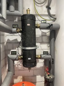
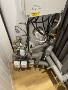
It’s 10C outside according to Grant panel.
36.4C coming in according to my probe. 38C according to Grant panel (using the hold down return, see value 9)
Living 2 rads
small - 30.6C / 29.1C - 1.5C
large - 27.5C / 29.3C - 1.8C
living 1 rad (ran out of probes lol, will get some more as this is useful)
30.6C / 28.1C - 2.5C
This room tends to be warmer by 1C. Note this rad is smaller than the largest one in living 2
Attached 6 probes now to largest rad in Living 2 – temps whilst ASHP runs (think caught just at a peak of a cycle, Grant panel said 39C in, I think out was 34-35C - cycle lasted I think around 25 mins, but not 100%)
Temp in room before I heard ASHP running - 18.8C, temp at peak of run - 19.1C
- Temp top right of LLH - 36.1C
- Temp just before heating zone - 35.6C
- Temp lock shield side just before rad - 28.9C
- Temp TRV shield side just after rad - 27C (1.9C diff)
- Temp lower left on rad - 26.9C
- Temp upper left on rad - 32.7C (5.8C diff)
- Temp lower right on rad - 27.4C
- Temp upper right on rad - 33.1C (5.7C diff)
Temps whilst ASHP isn't running:
- Temp lock shield side just before rad - 25.7C
- Temp TRV shield side just after rad - 24C
- Temp lower left on rad - 24.8C
- Temp upper left on rad - 28.1C
- Temp lower right on rad - 24.6C
- Temp upper right on rad - 28.3C
From that there's a temp diff between higher to lower portions of rad, across width of the rad seems consistent.
I'm going to play with the secondary pump speed to see what effect it has on temps in this room.
Posted by: @crimsonIt’s 10C outside according to Grant panel.
36.4C coming in according to my probe. 38C according to Grant panel (using the hold down return, see value 9)
Living 2 rads
small - 30.6C / 29.1C - 1.5C
large - 27.5C / 29.3C - 1.8C
living 1 rad (ran out of probes lol, will get some more as this is useful)
30.6C / 28.1C - 2.5C
This room tends to be warmer by 1C. Note this rad is smaller than the largest one in living 2
Because fractions of one degree can become important, I would suggest that you start by numbering each of your temperature sensors, fastening all the probes together with a rubber band or similar, then placing the probes into containers of water at different temperatures. Allow the readings to stabilise and ascertain how each sensor differs from the others, these correction values can then be used when obtaining readings.
I would suggest using three containers of water one at indoor ambient temperature, one at approximately 30C, and one at approximately 40C.
When taking readings it is obviously important to make good thermal contact between the probe and the pipework. You could try placing the probe on the pipework, then wrapping both with Aluminium foil which can then be covered with clingfilm or insulation tape, the normal pipe insulation can then be replaced over this arrangement.
Based upon your stated Living Room 1 requirement of 1063W at say -3C OAT, then the thermal energy required to maintain the IAT at 21C would be approximately 44W for each 1C that OAT is below 21C, ignoring all other factors. The heating demand at an OAT of 10C would therefore be approximately 490W.
To achieve this quantity of thermal energy output using the two Stelrad radiators would require an average radiator water temperature of 31.86C, which with a DT of say 2C would need a flow temperature of 32.86C and a return temperature of 30.86C.
If the Eskimo correction factors are correct, then an average Eskimo radiator water temperature of just below 30C would be required, so a flow temperature of 31C and a return temperature of 29C should be adequate.
I would suggest checking all the temperature sensors as detailed above. Installing them on the LLH and radiator pipes again as detailed above. Then monitor the operation of your system noting variations in the temperature readings from the heat pump restarting to it shutting down again.
Then post the results for analysis.
@crimson You are fighting a loosing battle, the low loss headers and the high temperature zone valves are tying both arms and 1 leg behind your back. Get rid of them, then you will see a completely different outcome. Unfortunately, the Grant unit is not the best and very difficult to get good performance from, but with some effort, it can be achieved.
If you cannot get a room up to temperature, it can only be, undersized radiator, undersized heat pump, insufficient temperature (looking at those readings it is not that, they are a lot higher than I would expect them to be with the currrent outdoor temperature) or insufficient flow of water, which I suspect is your problem.
Yeah, far as the heat specialist's recommendation goes it's get larger emitters to reduce flow temp and increase efficiency.
The ASHP cycling is pretty brutal, temps are higher at the moment as I've squashed the WC curve slightly to see its effect but not a huge one.
In terms of flow of water - heat specialist actually changed that down, was 36l/min, now 28l/min, he was here a good few hours and was monitoring the length of ASHP cycles with changes trying to get them longer by creating the heat dump and adjusting the ASHP speed and secondary pump speed etc.
At this rate I suspect my only course is to keep pushing for the larger rads with the builder. Not sure how a buffer tank will have as big an impact. I suspect intention there is to force a greater temp diff to keep the ASHP cycling longer.
The zone valves other than underfloor are manually on. I'm also wary of that LLH, fact when it was backwards installed caused issues, and still I see odd results on the temp probes (not done the check of variations yet, but 2 on the top left show same thing, it's not as warm as just before the heating zone, so either mixing or just that particular portion of the pipe isn't giving as much heat).
As for the Grant unit, I'd agree, it's a pain to adjust settings, and I can see it cycles off when really there's still a temp difference being shown so it can't modulate very low.
It's one zone that's not performing, it has the smallest rads, others zones can easily hit temps, so logic would state just up the size of them.
@crimson Possibly, but I still think it is a water flow issue looking at the pictures. You will find a huge difference removing the low loss header and all other pump, the grant has a reasonable pump in it and should be man enough, with a little balancing to do the job. You will find, with your underfloor (remove ALL the actuators) the unit will cycle significantly less.
Posted by: @crimsonYeah, far as the heat specialist's recommendation goes it's get larger emitters to reduce flow temp and increase efficiency.
The ASHP cycling is pretty brutal, temps are higher at the moment as I've squashed the WC curve slightly to see its effect but not a huge one.
In terms of flow of water - heat specialist actually changed that down, was 36l/min, now 28l/min, he was here a good few hours and was monitoring the length of ASHP cycles with changes trying to get them longer by creating the heat dump and adjusting the ASHP speed and secondary pump speed etc.
At this rate I suspect my only course is to keep pushing for the larger rads with the builder. Not sure how a buffer tank will have as big an impact. I suspect intention there is to force a greater temp diff to keep the ASHP cycling longer.
The zone valves other than underfloor are manually on. I'm also wary of that LLH, fact when it was backwards installed caused issues, and still I see odd results on the temp probes (not done the check of variations yet, but 2 on the top left show same thing, it's not as warm as just before the heating zone, so either mixing or just that particular portion of the pipe isn't giving as much heat).
As for the Grant unit, I'd agree, it's a pain to adjust settings, and I can see it cycles off when really there's still a temp difference being shown so it can't modulate very low.
It's one zone that's not performing, it has the smallest rads, others zones can easily hit temps, so logic would state just up the size of them.
If you read back in the thread I did suggest changing the LLH into a small volumiser rather than fully removing, but maybe something to consider once the heating season has ended. If the flow rate has been reduced in the primary circuit then it will also be necessary to do the same in the secondary circuit.
I would always recommend larger heat emitters if at all possible, though the capacity in each room should be selected to match the heat loss at a given LWT, it is quite pointless having large emitters in one or two rooms if they then have to be throttled back to balance with the other rooms.
Thanks @heacol
Just asked the specialist on thoughts of removing the LLH as a first step to see affect. His response was that "they're recommended by Grant as they don't have flow protection in their units. Also direct piped could cause excessive defrosting due to cold water coming back from the rads."
Just sharing what he's told me.
@crimson I know they would say that, all Grant is interested in is stopping their unit from suffering low flow errors, they do not care about you and your running costs. I have removed many low loss headers on grant units, and they do work reasonably well.
Thanks @heacol
Next step is now the builder is getting the plumbers and architect and myself to meet on site to discuss all this. This is the original plumbers, not the heat specialist.
I've been very adamant on it, all zones bar the downstairs work, and trying to run hot to compensate isn't something I want to do (it just makes it hard to modulate upstairs etc too and is massively inefficient).
Taking a step back, ignore other issues. What is a reasonable expectation here? 45C top of a weather curve with a house that has a large zone of underfloor, but another consisting of rads.
I'm just thinking as a default expectation with a weather curve to ascertain what would be reasonable, considering all the other work that's gone into the property - new extension that should perform well, underfloor heating, 75-100mm internal insulation, triple glazing etc. Fully re-done heating system and plumbing.
It's just very difficult to get into their heads, if you clearly have 2 zones performing well (and I suspect could run them sub 45C), to have one so obviously off and the ASHP cycling so much, that there's a fundamental problem.
I've every now and then tried to manipulate the W/C, and from what I'm seeing comments wise it's running quite hot now.
These settings are almost same as default - produce 18.5C consistently in mornings of downstairs living room (other zones hit temps fine) - outdoors has ranged from -1c to 12C lately:
2014 - minimum ambient temp: -3C
2103 - minimum water temp: 30C
2105 - maximum ambient temp: 20C
2102 - maximum water temp: 45C
I'm trying today. But may just run without W/C and see what temp the ASHP needs to be with 8-10C outside.
2014 - minimum ambient temp: -3C
2103 - minimum water temp: 35C
2105 - maximum ambient temp: 20C
2102 - maximum water temp: 45C
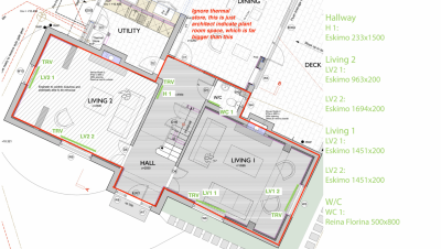
I thought going forward I would indicate on a segment of the floor plan the downstairs zone, what it comprises of, where rads are, what rads they are and which side TRVs are on (can't tell with the towel rad):
I've ordered 8 more probes (Derek I still haven't had time to denote their variations yet, but will get to that one day - I haven't forgotten).
At the moment I've placed probes either side of each of the 4 living room rads, to try and get an understanding of how much heat proportionally is in/out of the rads as suggested broadly. And also to see if there's any oddities.
will report back on findings.
One thing that's still in back of my mind. The clunking radiator LV2 2. This is the one with flow indicated as wrong way round, higher temp lock shield side versus TRV side. I'm also seeing it's always cooler than the other 3 living room rads across both rooms, which just seems odd, as I'd expect looking at the layout, that this is the 3rd radiator in the downstairs loop (H1 LV2 1, LV2 2) - I'll confirm this next time the ASHP comes on from cycling off, which rads heat up first when I have more probes. This to me might indicate an issue in this zone caused at this point. Seeing as the plumbers across the project have managed to:
1) Leave a cap off the LLH - flooding the utility
2) Leaving valves turned off in plant room
3) Install the LLH wrong way round
4) Get pipe centres wrong - and find the day they installed these Eskimo rads that this had to be quickly rectified
5) Numerous other seriously basic issues
I could imagine something very stupid has been done with it. I did note before upon people mentioning check lock shields, that this one was turned down compared to others (I've fully opened it now).
Also this is in the poorer performing of the 2 rooms.
- 27 Forums
- 2,495 Topics
- 57.8 K Posts
- 722 Online
- 6,220 Members
Join Us!
Worth Watching
Latest Posts
-

RE: Electricity price predictions
I agree incentives are needed. We are an unusual home b...
By Batpred , 4 hours ago
-
RE: Testing new controls/monitoring for Midea Clone ASHP
@tasos interesting. I might look into that. My other op...
By benson , 5 hours ago
-
RE: Our Experience installing a heat pump into a Grade 2 Listed stone house
@robs Do you need IAT for this to work? Don’t curren...
By Travellingwave , 7 hours ago
-
RE: Struggling to get CoP above 3 with 6 kw Ecodan ASHP
@goodbyegas Hi Fellow Ecodan owner here. Looking a...
By Travellingwave , 8 hours ago
-

RE: Say hello and introduce yourself
You can send private messages via the Messages (envelop...
By cathodeRay , 11 hours ago
-
RE: Peak Energy Products V therm 16kW unit heat pump not reaching flow temperature
With complete radio silence from Peak and no sign of th...
By DaveC , 11 hours ago
-
RE: Humidity, or lack thereof... is my heat pump making rooms drier?
Yes, ours dropped by about 25% RH. I figured it was a c...
By Papahuhu , 13 hours ago
-
RE: The Hidden Secret to a Successful Heat Pump: Pipe Size Matters
I'm wondering if I need to do any pipe upgrades. My hea...
By Falesh , 13 hours ago
-
RE: Solis inverters S6-EH1P: pros and cons and battery options
@batpred The Pace BMS also isn't the best with it's ...
By Bash , 13 hours ago
-

I understand now what you were referring to. This look...
By trebor12345 , 13 hours ago
-
RE: What determines the SOC of a battery?
@batpred I would consider changing your balance star...
By Bash , 14 hours ago
-

RE: Setback savings - fact or fiction?
This illustrates what I am getting at, even apparent st...
By cathodeRay , 18 hours ago
-

No you arent, because you dont need any, and furthermor...
By JamesPa , 19 hours ago
-

RE: Oversized 10.5kW Grant Aerona Heat Pump on Microbore Pipes and Undersized Rads
As I mentioned earlier most radiators have a power outp...
By JamesPa , 19 hours ago
-

@painter26 — they (the analogue gauges) are subtly diff...
By cathodeRay , 1 day ago
-

RE: Getting ready for export with a BESS
I would have not got it if it was that tight
By Batpred , 2 days ago
-
RE: Need help maximising COP of 3.5kW Valiant Aerotherm heat pump
@judith thanks Judith. Confirmation appreciated. The ...
By DavidB , 2 days ago
-

RE: Recommended home battery inverters + regulatory matters - help requested
That makes sense. I thought better to comment in this t...
By Batpred , 2 days ago
-
Bosch CS5800i 7kW replacing Greenstar Junior 28i
My heat pump journey began a couple of years ago when I...
By Slartibartfast , 3 days ago
-

RE: How to control DHW with Honeywell EvoHome on Trianco ActiveAir 5 kW ASHP
The last photo is defrost for sure (or cooling, but pre...
By JamesPa , 3 days ago
-

RE: Plug and play solar. Thoughts?
Essentially, this just needed legislation. In Germany t...
By Batpred , 3 days ago
-
RE: A Smarter Smart Controller from Homely?
@toodles Intentional opening of any warranty “can of wo...
By Papahuhu , 3 days ago
-
RE: Safety update; RCBOs supplying inverters or storage batteries
Thanks @transparent Thankyou for your advic...
By Bash , 3 days ago


