Posted by: @crimsonCan ignore that, I must have gone down to check at wrong time. It's 38C which is about right now, return is 36C, so it's close already. No doubt will turn itself off shortly giving no time for anything to heat up.
Do you still have the buffer tank?
If the heat pump controller is indicating a small DT but the heat emitters are not emitting sufficient thermal energy, then not all the flow is getting to the heat emitters or possibly mixing is occurring within the buffer tank.
Posted by: @derek-mPosted by: @crimsonI believe this is in reference to what they originally designed which was as an example:
A Stelrad Concord Lo-line 296x1600
v
A Eskimo 200x1694
I believe they're referring to the actual water capacity (builder said it's like 1/4 but taking that with a pinch of salt).
Found the 1/4 reference - this is by Eskimo themselves stating it uses 1/4 water volume compared to a steel rad.
According to the manufacturer's websites, the Stelrad is rated at 1784 Watts and the Eskimo at 1540 Watts, I assume at DT50.
What is the calculated heat loss for the rooms in question and the design flow temperature?
Living room 1: 1063W requirement
2x Stelrads at 1784W have 0.301 correction factor at D20 = 1063/0.301 = 3531 covered by 3568 from rads
2x Eskimo at 1320W (one room has smaller ones) have 0.41 correction factor at D20 = 1063 = 2592 covered by 2640 from rads
Eskimo correction factors here (in the download link) - https://www.eskimodesign.co.uk/technical-resources/correction-factors
I’ve been told the heat specialist double checked this but I’ll ask him as distrust what I’m told these days.
My suggestion has been to double the height to 400mm which would give 2x2457W v 2x1320W. Even at the more normal correction factor that would be a lot more output.
ATM the rad: basically get 30-45 min cycles to heat up and not often.
They’re proposing we add a buffer tank. Heat specialist did comment that the LLH seems physically short so probably doesn’t help with the Delta.
@crimson Derek is far more knowledgeable on these matters than I so I will sit back and read only now. Regards, Toodles.
Toodles, heats his home with cold draughts and cooks food with magnets.
Posted by: @toodles@crimson Derek is far more knowledgeable on these matters than I so I will sit back and read only now. Regards, Toodles.
Hi Toodles,
Sorry if I appear to be jumping in. I started writing a reply to the original post, but before I could complete, my Son called and we had quite a lengthy chat. Afterwards I completed the reply and posted, only to discover that you had been your usual helpful self.
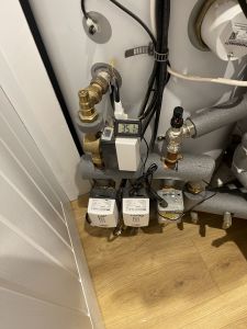
3 zone valves. Only one water pump in plant room, set to speed 2/3. Apologies don’t have a diagram.
1 zone valve manually on for upstairs heat dump.
downstairs is always calling for heat
Underfloor tends to hit temp and not calloften
@derek-m Not at all Derek, I’m OK on first line trouble shooting but have little in-depth knowledge of the more technical matters really. No offence taken at all - please carry on! Regards, Still Learning Daily, Toodles.
Toodles, heats his home with cold draughts and cooks food with magnets.
Posted by: @crimson3 zone valves. Only one water pump in plant room, set to speed 2/3. Apologies don’t have a diagram.
1 zone valve manually on for upstairs heat dump.
downstairs is always calling for heat
Underfloor tends to hit temp and not calloften
I assume that this water pump is after the LLH and supplying the various heat emitters via the 3 zone valves.
My understanding is that a LLH is like a small volume buffer tank, so it is necessary that the flow rate in and the flow rate out need to be reasonably well balanced, possibly slightly greater flow in than flow out.
I would suggest that you measure the temperatures on each side of the LLH and try to balance the flowrates, though this may be difficult if zone valves and TRV's are operating.
So the smaller rad in living 2:
30.6C in / 27.3c out - 3.3C diff
larger rad in Living 2
26.6C in / 29.4C out - wasn’t expecting that. This is the rad that keeps clanking. In temps are TRV side, out lock shield side. This was the rad that had to turn the lock shield quite a bit anticlockwise. Incase of note
Posted by: @derek-mPosted by: @crimson3 zone valves. Only one water pump in plant room, set to speed 2/3. Apologies don’t have a diagram.
1 zone valve manually on for upstairs heat dump.
downstairs is always calling for heat
Underfloor tends to hit temp and not calloften
I assume that this water pump is after the LLH and supplying the various heat emitters via the 3 zone valves.
My understanding is that a LLH is like a small volume buffer tank, so it is necessary that the flow rate in and the flow rate out need to be reasonably well balanced, possibly slightly greater flow in than flow out.
I would suggest that you measure the temperatures on each side of the LLH and try to balance the flowrates, though this may be difficult if zone valves and TRV's are operating.
sorry Derek, think I keep replying then not seeing all your posts. Same with Toodles.
water pump is after LLH before the zones yes.
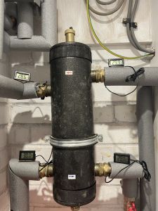
heat specialist tried to balance flow rates. I have a number of photos of the temps around the LLH. Seem to get the heat through after plumbers worked out LLH was wrong way round (yes it’s been that messy).
often what I’m seeing with milder temps is not a big different top right (coming in) and bottom right (going out). If there is it’s short lived hence the cycling of the ASHP.
this is something the specialist commented on. With the LLH being so physically short it’s not helping maintain a difference to modulate at lower temps.
Photo attached but ASHP not actually running at this point
The direction of water flow through the larger radiator would appear to be in reverse, which could be part of the problem. My understanding of radiators is that where the inlet and outlet pipes connect near the bottom, the flow from the inlet pipe is directed up one or two of the vertical tubes to the top header, which runs the full length of the radiator.
The top header is therefore filled with warm water, which gradually flows down the remaining vertical tubes to the bottom header, which in turn is connected to the outlet pipe. The warm water therefore flows slowly down most of the vertical tubes distributing thermal energy as it does so.
If the water flow is in reverse, it could be that only certain parts of the radiator are fully being warmed and therefore distributing thermal energy into the room. This may be apparent if you have a thermal camera or measure the surface temperature at various points.
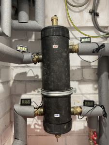
It would be useful to see the LLH temperatures with the system operating.
Will see if can do some surface temps of that rad when ASHP is running at some point today.
Photo attached of LLH whilst ASHP running this AM. I’m going to check the top left probe as it doesn’t report same temp as just before heating zone on the same pipe. Will move it as probably not getting as good a connection.
- 27 Forums
- 2,495 Topics
- 57.8 K Posts
- 645 Online
- 6,220 Members
Join Us!
Worth Watching
Latest Posts
-

RE: Electricity price predictions
I agree incentives are needed. We are an unusual home b...
By Batpred , 2 hours ago
-
RE: Testing new controls/monitoring for Midea Clone ASHP
@tasos interesting. I might look into that. My other op...
By benson , 3 hours ago
-
RE: Our Experience installing a heat pump into a Grade 2 Listed stone house
@robs Do you need IAT for this to work? Don’t curren...
By Travellingwave , 5 hours ago
-
RE: Struggling to get CoP above 3 with 6 kw Ecodan ASHP
@goodbyegas Hi Fellow Ecodan owner here. Looking a...
By Travellingwave , 6 hours ago
-

RE: Say hello and introduce yourself
You can send private messages via the Messages (envelop...
By cathodeRay , 9 hours ago
-
RE: Peak Energy Products V therm 16kW unit heat pump not reaching flow temperature
With complete radio silence from Peak and no sign of th...
By DaveC , 9 hours ago
-
RE: Humidity, or lack thereof... is my heat pump making rooms drier?
Yes, ours dropped by about 25% RH. I figured it was a c...
By Papahuhu , 11 hours ago
-
RE: The Hidden Secret to a Successful Heat Pump: Pipe Size Matters
I'm wondering if I need to do any pipe upgrades. My hea...
By Falesh , 11 hours ago
-
RE: Solis inverters S6-EH1P: pros and cons and battery options
@batpred The Pace BMS also isn't the best with it's ...
By Bash , 11 hours ago
-

I understand now what you were referring to. This look...
By trebor12345 , 11 hours ago
-
RE: What determines the SOC of a battery?
@batpred I would consider changing your balance star...
By Bash , 12 hours ago
-

RE: Setback savings - fact or fiction?
This illustrates what I am getting at, even apparent st...
By cathodeRay , 16 hours ago
-

No you arent, because you dont need any, and furthermor...
By JamesPa , 17 hours ago
-

RE: Oversized 10.5kW Grant Aerona Heat Pump on Microbore Pipes and Undersized Rads
As I mentioned earlier most radiators have a power outp...
By JamesPa , 17 hours ago
-

@painter26 — they (the analogue gauges) are subtly diff...
By cathodeRay , 1 day ago
-

RE: Getting ready for export with a BESS
I would have not got it if it was that tight
By Batpred , 2 days ago
-
RE: Need help maximising COP of 3.5kW Valiant Aerotherm heat pump
@judith thanks Judith. Confirmation appreciated. The ...
By DavidB , 2 days ago
-

RE: Recommended home battery inverters + regulatory matters - help requested
That makes sense. I thought better to comment in this t...
By Batpred , 2 days ago
-
Bosch CS5800i 7kW replacing Greenstar Junior 28i
My heat pump journey began a couple of years ago when I...
By Slartibartfast , 2 days ago
-

RE: How to control DHW with Honeywell EvoHome on Trianco ActiveAir 5 kW ASHP
The last photo is defrost for sure (or cooling, but pre...
By JamesPa , 2 days ago
-

RE: Plug and play solar. Thoughts?
Essentially, this just needed legislation. In Germany t...
By Batpred , 3 days ago
-
RE: A Smarter Smart Controller from Homely?
@toodles Intentional opening of any warranty “can of wo...
By Papahuhu , 3 days ago
-
RE: Safety update; RCBOs supplying inverters or storage batteries
Thanks @transparent Thankyou for your advic...
By Bash , 3 days ago


