Notifications
Clear all
Air Source Heat Pumps (ASHPs)
207
Posts
15
Users
54
Reactions
49.3 K
Views
13/04/2023 2:58 pm
When you say "After writing as directed in the manual, I seem to be getting [near] real time data from the flow sensor" I find myself confused. As I understand it, modbus is a two way connection, you can either write to, or read from, the device.
I should have been clearer ... and this is Samsung specific ... The modbus module MIM-B19M does not know how to talk to the heat pump to respond to some register requests ( 'new registers" in the manual so likely don't exist on air conditioners). You need to do a one time programming of these so that when you try to read the new registers the MIM-B19M module knows what internal commands to send, and where to send them (either the wired remote control or the heat pump itself) likely some Samsung specific protocol or modbus on a different "network", I am not sure which.
My main point is that incorrectly setting up those registers by configuring them one at at time created very strange behavior as shown in the chart, not that different to what you are experiencing. You have to program all the registers in one go (at least all for the heat pump in one go, and all for the internal remote control in a second go).
So the details not relevant to you, other than, similar strange behaviour fixed by setting up the config of the MIM-B19M correctly.
1
13/04/2023 2:59 pm
Having done that, you are then able to read the data you're after.
Exactly, but Samsung specific, of course.

Topic starter
13/04/2023 3:01 pm
@derek-m - thanks, brilliant clear explanation. Especially as I still have an analogue CRT TV! Looks right and works well in an old leaky listed building...
Midea 14kW (for now...) ASHP heating both building and DHW
Topic starter
13/04/2023 3:05 pm
Exactly, but Samsung specific, of course.
But why not go for a generic approach, that can be adapted where necessary for manufacturer quirks and irritations? As long as you have a physical modbus connection available, and the manufacturer's table of modbus register addresses, then you should be able to connect and get (and even set) data.
There is still the data is wrong can of worms to be dealt with, but at least you have something to work with.
Midea 14kW (for now...) ASHP heating both building and DHW

13/04/2023 3:07 pm
The 120 Ohm resistor at the end of the transmission line is to prevent signal reflection.
In practice you will find that a client connected to a single server doesn't care whether the 120R is or isn't there.
It becomes a problem when you add another server because the interference causes packet errors.
Beware. On the 30 or so Modbus servers I'm presently working with, there are three ways they now handle the 120R resistor.
- the pcb has no 120R on board. You add it in parallel to the A & B wires when you make the end connection on the string
- the pcb has a 120R on board, which is open-circuit by default. You either move across a jumper, or else make a solder bridge between two pads, to 'enable' the resistor
- the pcb has a 120R on board. You snip it out or run a sharp knife across a pcb-track to remove it
Intuitive stuff, this Modbus/RS485, isn't it?!
Save energy... recycle electrons!
Topic starter
13/04/2023 3:09 pm
You need to do a one time programming of these so that when you try to read the new registers the MIM-B19M module knows what internal commands to send
Ah, that makes it all clear. Thanks very much. I thought you had to send a write request before each read request, which did seem odd, but a one time programming message makes sense.
Midea 14kW (for now...) ASHP heating both building and DHW
13/04/2023 4:20 pm
Additional info on pull down end of line reistors:
To eliminate the presence of reflections from the end of the cable, it must be terminated at both ends with a resistor across the line (between + and -), in accordance with its characteristic impedance. Both ends must be terminated since the direction of propagation is bidirectional.
In case of an RS485 twisted pair cable this termination is typically between 120 and 130 Ω.
Here is a simple schematic of how the end of the lines should be terminated:
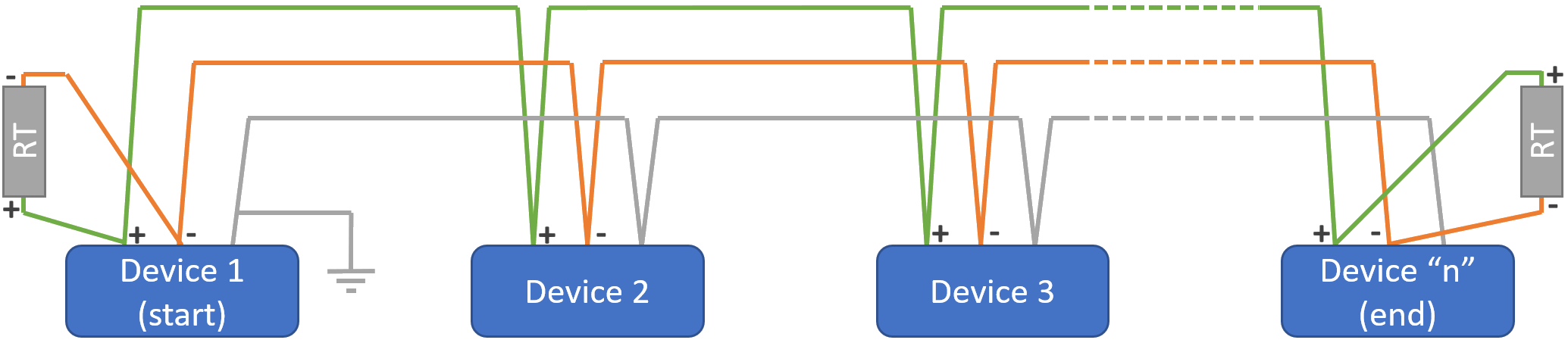
"RT" is the 120 Ω termination resistor.
"Device 1" on a Modbus network is the Master device initiating communication.
Bias resistors
With RS485 networks, there are periods of time when no driver is actively driving the bus. On a Master-Slave network this would correspond to potential times when the Master is not transmitting and the slaves have finished responding to any command.
This state is also called "tri-state mode".
During this time, the termination resistors collapse the differential bus voltage to 0V, which is an undefined input level for many RS485 receivers. Faced with this undefined input, a receiver might output the wrong logic state or worse yet, it might oscillate. The oscillation may be interpreted as an endless stream of message start bits, causing the controller to waste valuable bandwidth trying to service these phantom messages. Fail-safe bus biasing is one way to alleviate this problem.
The objective of biasing is to make sure that the RS485 line remains in a known, non-fluctuating state when no devices are transmitting. Biasing the entire network requires a single pair of resistors: a pull-up resistor to +5V attached to the "+" signal line, and a pull-down resistor to ground attached to the "-" signal line.
See the schematic here below which explains how biasing is achieved:
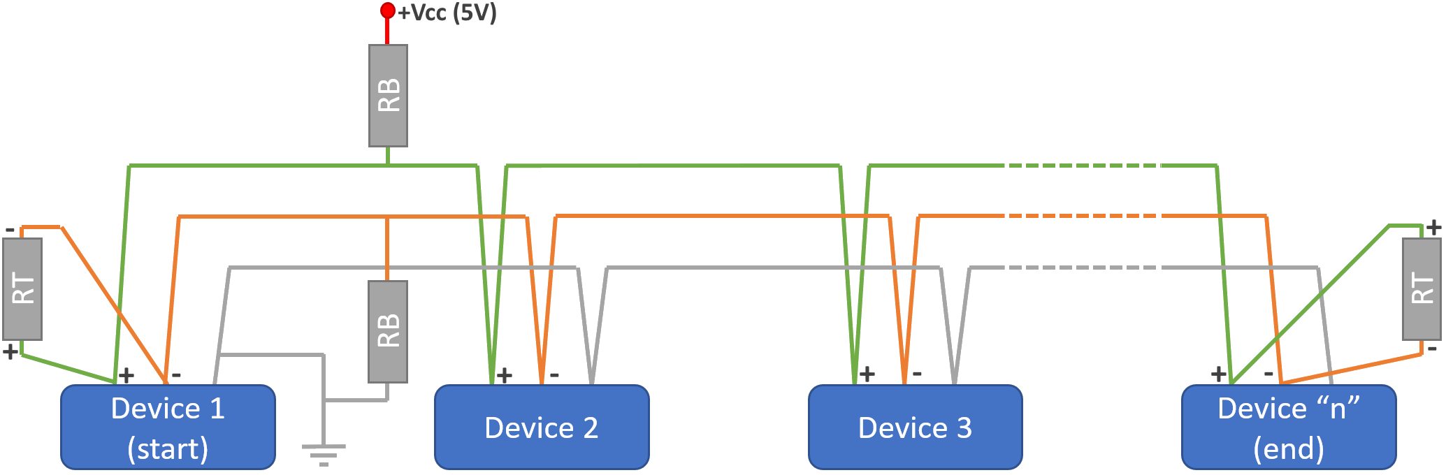
The "RB" going between "-" and "earth" is the "pull-down" resistor, the "RB" going between "+" and "+Vcc(5V)" is the "pull-up" resistor.
13/04/2023 6:55 pm
Sorry @iaack but I'm wary of suggesting the use of bias resistors on an open forum without a number of caveats being stated.
Let me just mention a few:
1: RS485 (technically TIA485) is designed to be a floating differential-voltage bus network. The 'standard' includes devices having an Earth (reference) connection in addition to the A & B pins. However, this earth may not be the same as the safety earth on connected equipment, nor can it be inferred that the RS485 earth connection is at 'zero volts'.
2: RS485 has a line limit of 1.2km. Over that distance there will be devices with RS485 which are being operated at different voltages. Buildings a kilometer apart may have mains supplies which differ by 6 volts or so. It is important the the A & B lines are allowed to float, without an earth reference. Any attempt to define an earth reference needs to done in such a way that it only occurs at one point, otherwise a current will flow through the earth wire. If bias resistors are present, the A and/or B wires may also carry current.
Currents on the wires can burn out RS485 interfaces.
They can also provide a 'false' earth response for equipment where the mains (safety) earth is itself faulty/absent.
3: Tying a bias resistor to +5v is also fraught.
Which 5v are we referring to, and on which piece of equipment?
In any case, the A & B wires on RS485 are permitted to float plus/minus 7v away from the optional earth connection.
4: RS485 interfaces are permitted to be opto-isolated from the logic electronics within a device. In such a case neither earth nor +5v makes any sense.
5: When a location suffers surges due to back-EMF from motors or nearby lightning strikes, the surge current will find the quickest way to earth. If you present it with an earth on a digital network, it will quite happily use it to jump between devices on that network. In the majority of cases, the electronic equipment will survive, but the network interfaces suffer intermittency. That's a nightmare to fault-find!
Heat pumps have such motors. There will be back-EMF when motors switch off.
You don't want any of that current 'seeing' a path to earth through your RS485 network.
Returning to my point-2, you might surmise that the 0v voltage references on connected devices are likely to vary only on longer RS485 network.
My experiments over the past few months have shown this not to be the case.
I'm connecting RS485 between equipment related to off-grid battery storage.
Although there are (two) earth connections to each off-grid mains-connected inverter, there can be several volts difference between each battery bank in the same room.
This isn't a fault. It can be due to a number of factors including high charge currents, type-T fuses and over-current protection devices.
The whole point of using Modbus over RS485 in these circumstances is that it is floating.
It will continue to operate properly, regardless of what each connected device presents as 'zero volts'.
In conclusion, I'm happy that RS485 can have bias resistors incorporated.
But there needs to be a reasonably good appreciation of what possible outcomes this may create.
Save energy... recycle electrons!
13/04/2023 8:29 pm
The obvious solution for energy in is to ignore the heat pump data altogether, and just use the external meter, but I have yet to set up optical counter.
Pulse counting is only suitable for energy because 1 pulse usually is 1 Wh. At 1.8kW you would get a pulse every 2 seconds. There are some good posts on HA and Open Energy Monitoring about reading Modbus energy meters.
Regarding my earlier post which you commented on, I don’t think you have taken note of my posts on my system and understand it. As I may have mentioned a few radiators are a bit small leading to a lack of balance. The pump is clearly not suitable for the secondary circulation system. The ASHP just sees a plate heat exchanger to avoid having glycol in the radiators. In the last post I was merely scoping the size of the installation, which is large by any standard (300m2 house). I will have to wait till next winter to get data on how it copes in cold weather. Unlike you I don’t run 24/7, but I do set back the temperature a few degrees at night, and at this time of year I try to heat the house up when it is warmer outside to benefit from greater efficiency.
Phil
Topic starter
14/04/2023 3:42 pm
I have been having another crack at my COP calcs, given that some of the trailing 60 minute values look suspiciously high at over 4 and sometimes even 5. But however I do the energy in/out calcs, average for the whole hour in one go, or calculate for each minute and then sum for the hour, I get the same results give or take very small differences. Perhaps looking at the relationship between ambient temp and COP might be revealing. If the values are valid, I expect to see a relationship between ambient temp, and the short answer is I do. Here are two plots. The first is hourly ambients and COPs over time, the second a scatter plot of COP against average ambient temp for each hour:


These charts don't prove the values are correct, but at the same time, the obvious correlation is consistent with them being correct. I suspect any tendency to overestimate COP may arise not in the calcs, but in the underlying data.
The energy out raw data (flow rate and LWT/RWT) are probably not far out. I say this because I have now discovered I have got an inline flow rate meter, very analogue, and awkward to read because of where it is, which is why I hadn't spotted it, but it is a flow rate meter, and the values tally with the Midea modbus values. Likewise, the LWT/RWT, and so their delta t, is pretty close to measured values. This only leaves the energy in raw data, amps and volts. Volts are pretty constant, leaving amps in as the most likely suspect. There's even a sort of smoking gun (values are all kWh except for % column):

These were the hourly comparisons you may recall I did a short while ago between the various ways of deriving energy in. The Midea app and the total lifetime 'now minus previous' methods both over-estimate usage, which we already suspected, but the calculated values under-estimate usage. As volts in are pretty constant, that just leaves amps in as the likely culprit. Unfortunately, it isn't a constant error, at least it isn't in this n=2 series of obs, so I can't on the basis of these factor in a correction. Maybe over longer periods the error will become more constant on average, and I will be able to apply a correction factor.
Any thoughts/comments very welcome as ever.
This post was modified 3 years ago by cathodeRay
Midea 14kW (for now...) ASHP heating both building and DHW
1
15/04/2023 9:02 am
Has anyone made sense of the TF Module Temperature ("Feedback on outdoor unit, unit: °C") on address 135?
Looking at the ambient temperature reported on address 107, the ambient temperature swings wildly by as much as 3°C during each cycle (not surprising given that the unit is dumping cold air), so I expected the feedback to be some kind of offset to account for that, but the number I get back is too high, I've observed values in the range 18-22
15/04/2023 10:32 am
Please to be able to share this.
Here's a working Node-RED modbus configuration for Home Assistant. It supports general sensors for:
- Power in
- Heat out
- Ambient temperature
- Compressor discharge temperature
- Compressor operating frequency
- Hot water tank temperature
- Fan speed
- Leaving water temperature
- Returning water temperature
Also has diagnostic sensors for:
- Zone 1 Weather compensation lower ambient and upper flow (i.e. low end of the curve)
- Zone 1 Weather compensation upper ambient and lower flow (i.e. high end of the curve)
- Zone 1 Calculated target flow temperature using the curve
- Error code
And diagnostic binary sensors for:
- Anti-freezing
- Compressor
- Defrosting
- Internal pump
- External pump
- Heating solenoid valve
- Hot water solenoid valve
- Oil return
As well as controls for:
- Eco mode (although I'm still none the wiser as to what this actually does)
- Zone 1 Heating toggle
- Hot water toggle
- Zone 1 weather compensation toggle
I don't have a second zone so I have not configured any of the Zone 2 addresses.
If you're using the Home Assistant Node-RED addon, you should be able to download the following configuration, and import to Node-RED to get started: https://gist.github.com/benlancaster/3c416d8e0cb9f3c1ea22beb921f4a48a
If I get a chance, I will go through and update the Description blocks for all the pertinent sections. There's lots to improve still, so it may change, but I'm minded to go down the route of creating a "proper" integration now that I have a working reference integration.
Many caveats:
- The sensor names are not particularly well done (they don't have a common prefix)
- "It works on my machine", it may very well not work on yours
- Zero warranty
- ... probably more
Consider it licensed under WTFPL.
1

Latest Posts
-

RE: Solis inverters S6-EH1P: pros and cons and battery options
@jancold I only discuss data.. Fogstar were not impress...
By Batpred , 11 minutes ago
-
RE: What determines the SOC of a battery?
@batpred Ironically you didn't have anything good to...
By Bash , 45 minutes ago
-
RE: Testing new controls/monitoring for Midea Clone ASHP
Here’s a current graph showing a bit more info. The set...
By benson , 59 minutes ago
-
RE: Setback savings - fact or fiction?
True there is a variation but importantly it's understa...
By RobS , 59 minutes ago
-

Below is a better quality image. Does that contain all ...
By trebor12345 , 1 hour ago
-
Sorry to bounce your thread. To put to bed some concern...
By L8Again , 1 hour ago
-

@painter26 — they (the analogue gauges) are subtly diff...
By cathodeRay , 2 hours ago
-
RE: Electricity price predictions
I am always impressed with how you keep abreast of so m...
By Batpred , 3 hours ago
-
RE: Humidity, or lack thereof... is my heat pump making rooms drier?
@majordennisbloodnok I’m glad I posted this. There see...
By AndrewJ , 3 hours ago
-
Our Experience installing a heat pump into a Grade 2 Listed stone house
First want to thank everybody who has contributed to th...
By Travellingwave , 6 hours ago
-
RE: Struggling to get CoP above 3 with 6 kw Ecodan ASHP
Welcome to the forums.I assume that you're getting the ...
By Sheriff Fatman , 9 hours ago
-
RE: Say hello and introduce yourself
@editor @kev1964-irl This discussion might be best had ...
By GC61 , 10 hours ago
-

RE: Oversized 10.5kW Grant Aerona Heat Pump on Microbore Pipes and Undersized Rads
@uknick TBH if I were taking the floor up ...
By JamesPa , 1 day ago
-
RE: Getting ready for export with a BESS
I would have not got it if it was that tight
By Batpred , 1 day ago
-
RE: Need help maximising COP of 3.5kW Valiant Aerotherm heat pump
@judith thanks Judith. Confirmation appreciated. The ...
By DavidB , 1 day ago
-
RE: Recommended home battery inverters + regulatory matters - help requested
That makes sense. I thought better to comment in this t...
By Batpred , 1 day ago
-
Bosch CS5800i 7kW replacing Greenstar Junior 28i
My heat pump journey began a couple of years ago when I...
By Slartibartfast , 1 day ago
-
RE: How to control DHW with Honeywell EvoHome on Trianco ActiveAir 5 kW ASHP
The last photo is defrost for sure (or cooling, but pre...
By JamesPa , 1 day ago
-
RE: Plug and play solar. Thoughts?
Essentially, this just needed legislation. In Germany t...
By Batpred , 1 day ago
-
RE: A Smarter Smart Controller from Homely?
@toodles Intentional opening of any warranty “can of wo...
By Papahuhu , 1 day ago
-
RE: Safety update; RCBOs supplying inverters or storage batteries
Thanks @transparent Thankyou for your advic...
By Bash , 1 day ago
-
RE: Air source heat pump roll call – what heat pump brand and model do you have?
Forum Handle: Odd_LionManufacturer: SamsungModel: Samsu...
By Odd_Lion , 1 day ago
-
RE: Configuring third party dongle for Ecodan local control
Well, it was mentioned before in the early pos...
By F1p , 2 days ago


