Help required with Mitsubishi engineer report...
We moved into a new build property in 2020 and it has a 14kw Mitsubishi air source heat pump.
Our bills during winter are astronomical and I’d like to try and improve the efficiancy of our system.
I called Mitsubishi (rather than the company that installed the system) and asked them to send an engineer to review the work that had been carried out and possibly identify any mistakes that had been made.
From my very limited knowledge and rummaging around on google I’m not sure that everything in the report is accurate / correct.
Could anyone with some knowledge on the matter please review the report and let me know their thoughts? I'd like to try and determine how accurate it is before discussing with the installers.
Ive pasted the report below and I’ve added my (probably moronic) commets in brackets…
General info:
ASHP model: Mitsubishi PUHZ-HW140VHA2
Tank: EHPT30X-UKHCW (300L pre-plumbed standard)
Underfloor heating downstairs, 2 manifolds roughly 180sq meters of floor
6 Rads upstairs.
JG Aura stats
Happy to provide more info / pictures if it helps.
Mitsibushi engineer report:
- Customer has higher than expected running costs.
- 14kw outdoor unit on 22mm primary pipework - this should be 28mm.
- (engineer stated that the pipework from the ashp to the tank should be 28mm all the way or the ashp is ‘working too hard’)
- Minimum system water quantity has not been met, as the Ecodan and cylinder are back to back, so a buffer or Low-loss header should of beenused - The minimum water quantity should be 60L.
- (Ive tried to find the minimum water quantity for the models i have and from what i can see i think it needs 100L not 60L? Also, does this minimum water quantity mean the amount in the entire unfloor system or just the amount between the ashp and the tank as he suggests? The ASHP is directly behind the tank on the other side of the wall and its a very short run of pipework)
- UFH Manifolds contain local blending valves, zone valves and pumps. Blending valves should be removed to maximise efficiency and local zone valves and pumps should be wired back to the FTC.
- (The engieer told me that the blending valves are cooling down the water that ive paid to head up - this doesnt seem true from what ive found online and people seem to suggest using blending valves to protect the flooring?)
- Currently the diverter valve is passing to heating during hot water operation due to UFH Pumps not being controlled by the FTC.
- (Engineer said that because the manifolds / pumps are not wired back to the FTC that the system is not able to run efficiently. He said that running the hot water (bath, shower etc) would leave the UFH ‘open’ and the hot water would run out, essentially depleting whats there and would have to heat the entire floor up again when the hot water is turned off. If the manifolds / pumps were wired back to the FTC then the system would be able to ‘close’ the UFH when the hot water is on to prevent the water running out)
- Currently one of the UFH control boards does not pass a signal back to the FTC for demand so the second manifold or rads needs to be on for the system to operate this manifold.
- (This is correct and seems like a balls up from the installers, all of the stats connected to one manifold cant send an ‘on’ signal so stats from the other manifold need to be on first)
- The UFH stats have pulse moderation activated - each stat will need to have pulse moderation disabled to stop the system cycling on and off.
- (No idea what this is but i think i have found something that might be relevant in the manual for the stats)
- Starts per hour are over 4.5 due to unit installation conditions.
- (I know that the system is constently starting up and shutting down during the colder months so this doesnt suprise me, question is what number should I be aiming for?)
- The unit is consuming more energy than expected due to the installation. The installation of the system needs to be corrected to optimise system performance and efficiency.
Posted by: @tobydehWe moved into a new build property in 2020 and it has a 14kw Mitsubishi air source heat pump.
Our bills during winter are astronomical and I’d like to try and improve the efficiancy of our system.
I called Mitsubishi (rather than the company that installed the system) and asked them to send an engineer to review the work that had been carried out and possibly identify any mistakes that had been made.
From my very limited knowledge and rummaging around on google I’m not sure that everything in the report is accurate / correct.
Could anyone with some knowledge on the matter please review the report and let me know their thoughts? I'd like to try and determine how accurate it is before discussing with the installers.
Ive pasted the report below and I’ve added my (probably moronic) commets in brackets…
General info:
ASHP model: Mitsubishi PUHZ-HW140VHA2
Tank: EHPT30X-UKHCW (300L pre-plumbed standard)
Underfloor heating downstairs, 2 manifolds roughly 180sq meters of floor
6 Rads upstairs.
JG Aura stats
Happy to provide more info / pictures if it helps.
Mitsibushi engineer report:
- Customer has higher than expected running costs.
- 14kw outdoor unit on 22mm primary pipework - this should be 28mm.
- (engineer stated that the pipework from the ashp to the tank should be 28mm all the way or the ashp is ‘working too hard’)
- Minimum system water quantity has not been met, as the Ecodan and cylinder are back to back, so a buffer or Low-loss header should of beenused - The minimum water quantity should be 60L.
- (Ive tried to find the minimum water quantity for the models i have and from what i can see i think it needs 100L not 60L? Also, does this minimum water quantity mean the amount in the entire unfloor system or just the amount between the ashp and the tank as he suggests? The ASHP is directly behind the tank on the other side of the wall and its a very short run of pipework)
- UFH Manifolds contain local blending valves, zone valves and pumps. Blending valves should be removed to maximise efficiency and local zone valves and pumps should be wired back to the FTC.
- (The engieer told me that the blending valves are cooling down the water that ive paid to head up - this doesnt seem true from what ive found online and people seem to suggest using blending valves to protect the flooring?)
- Currently the diverter valve is passing to heating during hot water operation due to UFH Pumps not being controlled by the FTC.
- (Engineer said that because the manifolds / pumps are not wired back to the FTC that the system is not able to run efficiently. He said that running the hot water (bath, shower etc) would leave the UFH ‘open’ and the hot water would run out, essentially depleting whats there and would have to heat the entire floor up again when the hot water is turned off. If the manifolds / pumps were wired back to the FTC then the system would be able to ‘close’ the UFH when the hot water is on to prevent the water running out)
- Currently one of the UFH control boards does not pass a signal back to the FTC for demand so the second manifold or rads needs to be on for the system to operate this manifold.
- (This is correct and seems like a balls up from the installers, all of the stats connected to one manifold cant send an ‘on’ signal so stats from the other manifold need to be on first)
- The UFH stats have pulse moderation activated - each stat will need to have pulse moderation disabled to stop the system cycling on and off.
- (No idea what this is but i think i have found something that might be relevant in the manual for the stats)
- Starts per hour are over 4.5 due to unit installation conditions.
- (I know that the system is constently starting up and shutting down during the colder months so this doesnt suprise me, question is what number should I be aiming for?)
- The unit is consuming more energy than expected due to the installation. The installation of the system needs to be corrected to optimise system performance and efficiency.
Hi Tobydeh,
Welcome to the forum.
I suspect from your comments that you are not yet a heat pump expert, so I will try to aim my answers at a not too technical level. If there is anything that you don't fully understand then please let me know. I will go through the basics first and leave the more technical issues for later.
1) I would probably agree with the Mitsubishi Engineer that the primary pipework should be at least 28mm, assuming that your home requires the full 14kW of thermal energy during periods of colder weather. In basic terms, each litre of water will transport a certain quantity of thermal energy from the heat pump to the heat emitters (UFH and radiators) within your home, so the more thermal energy that is required, the greater the water flow rate will need to be. The velocity of the water going through the pipework is dependent upon the flow rate and the internal diameter of the pipework, so the larger the pipe diameter, the lower the velocity. There are prescribed limits for the water velocity through the pipework, which should not be exceeded.
You should have been supplied with heat loss calculations for your home within the handover package. Could you please post a copy?
2) The minimum quantity of water required within the primary system is 20L for average/warmer climates and 60L for colder climates. I suspect that the UK may fall within the former, but you would need to read through the relevant EU directive to be certain. The primary purpose of having a sufficient quantity of warm water within the primary circuit is so that the heat pump can perform a defrost cycle.
It should be possible to obtain the quantity of water in each radiator by looking up the size and type on the Screwfix or similar website. If you know the length and diameter of the UFH pipes it should be possible to calculate the volume of those. Make an assessment of the length and diameter of all the connecting pipework, which will allow the volume to be calculated. Add them all together to obtain the overall capacity of the central heating system.
I do believe the heat pump itself contains approximately 5L of water, and the heating coil within the DHW cylinder contains at least 4.4L, plus the interconnecting pipework. Provided that there is sufficient warm water in the DHW cylinder, I would suspect that there is sufficient thermal energy available to perform the defrost cycle.
The fact that you have run the system for at least 1 Winter period would indicate that defrosting the heat pump is not a problem, and hence a buffer tank may not be required. Installing a buffer tank can reduce the overall system efficiency, so should only be done if absolutely necessary.
If you can identify how many water pumps you have fitted, and their location, I will go through the possible control aspects tomorrow. Also the location of your FTC controller and all thermostats.
Feels a little disappointing to me that a 3 year old home is having a 14kw heatpump fitted. Granted it's a sizeable property but I would have hoped insulation levels would have meant a much lower heat loss, quite possible it was oversized though I guess which would chime in with the other issues. I've seen most you can get down 22mm pipe is about 6kw heat so that does seem very wrong
Good luck with sorting it, I've seen Derek's a great sage on here full of helpful advice. Can you get done via NHBC?
Posted by: @tobydehUFH Manifolds contain local blending valves, zone valves and pumps. Blending valves should be removed to maximise efficiency and local zone valves and pumps should be wired back to the FTC.
It is a fundamental feature of ashps, traceable pretty directly to the laws of thermodynamics, that they are more efficient if the temperature of the water they supply ('flow temperature') is lower. For ufh you typically aim for a ft of 35C (less for most of the season). If you have blending valves then you are reducing the temp to the ufh relative to the ft from the ashp which means you must increase the ft from the ashp to get the same heat output, losing efficiency. The Mitsubishi engineer is right on this one (I had a quick look at the others, they are also very plausible)
Zone valves are also deprecated in ashp installations because they reduce the engaged system volume which causes excessive on/off cycling leading to inefficiency and also, slightly counter intuitively, it is often more efficient to heat the whole house than only part of it. There are exceptions, if you have a long thin house that nearly divided in two that might not be true, but for a near cube shaped house it probably is.
It sounds like the installer may have fitted an ashp to a ufh system designed for a gas boiler. Nothing that a bit of reworking can't fix, but stupid nevertheless
A 2020 house of 180 sq m can't possibly require 14kW unless insulation standards in building regs have been completely ignored (which would of course explain high heating bills!,). Mine is about the same size, was built in the 1930s, has had some later extensions and piecemeal insulation upgrades. It requires 9kW max (there is some uncertainty, the actual measured figure is 7.5kW). I think your 14kW unit Is almost certainly way over specified which will also cause poor performance.
How much electricity are you actually consuming for heating?
4kW peak of solar PV since 2011; EV and a 1930s house which has been partially renovated to improve its efficiency. 7kW Vaillant heat pump.
Posted by: @tobydehCurrently the diverter valve is passing to heating during hot water operation due to UFH Pumps not being controlled by the FTC.
Heating systems for HP's are set up so that the hp either supplies hot water to heat the dhw tank or hot (but generally cooler) water for the space heating, but not both at the same time. The reason for this is so that the hp can operate at one temperature when heating dhw, and another lower temperature when doing space heating, which is much more efficient. Most gas fired heating systems (in the UK, not in more enlightened countries eg Germany) operate on the same temp for both.
So if the heating system has been plumbed/wired so that is impossible, either it will be much less efficient, or it will heat dhw badly, or both.
4kW peak of solar PV since 2011; EV and a 1930s house which has been partially renovated to improve its efficiency. 7kW Vaillant heat pump.
Posted by: @tobydehThe UFH stats have pulse moderation activated - each stat will need to have pulse moderation disabled to stop the system cycling on and off.
OMG
Pulse modulation thermostats attempt to switch heat sources on/off in a 'clever' fashion to reduce temperature swings. It's debatable whether this is sensible even for fossil fuel boilers, for heat pumps it's a disaster.
More enlightened countries (eg Germany) have, for decades, had what is called 'weather compensation' on their boilers (ours also do of course, because the market is global, but we disable it). This achieves a similar (not strictly the same) end result as a pulse modulation thermostat, but in a way that makes the boiler operate more efficiently not less efficiently. Basically weather compensation adjusts the flow temp according to the outside temp thus attempting to match the emitter output to the demand, with the boiler operating near continuously but at a lower temp, which is the most efficient way to run it (even a gas boiler, but much, much more so a heat pump)
Heat pumps have weather compensation built in and it's mandatory to switch it on in the UK if the pump is installed under the standard industry rules (MCS). In this circumstance pulse modulating thermostats will upset the native heat pump control and should not be used. Actually the ideal arrangements is one where thermostats are rarely 'off' because the flow temp is just right for the outside temp so the emitter needs to be on continuously.
Again the Mitsubishi engineer is correct.
Overall I think that the Mitsubishi report proves that the system is incorrectly set up for use with a heat pump. I suspect you can also prove that the selection of heat pump is incorrect (I guess you need 8.5kW max not 14, but that would need to.be confirmed).
As to whether nhbc or the installer will sort it out - I wish you luck. It would be worth checking if he is MCS accredited, complaining to MCS might give some leverage if he is (although not guaranteed).
The good news is that it is likely at least part fixable without ripping out the whole system, starting by enabling/properly adjusting weather compensation, removing mixing valves, adjusting flow temperature, and fixing up the simultaneous dhw/space heating, disabling modulation on thermostats or just turning them up well above the target temp and allowing weather comp to do its job.
That will leave the (probably) oversized heat pump. Depending on how oversized it is this may not be a disaster, but there is a possibility it will need to be swapped out for a lower capacity unit to operate correctly.
Incidentally I'd find out the answer to the capacity issue before upgrading the 22mm pipes. If in fact your house requires only 6-8kW, which is not improbable, 22mm is sufficient unless you have very long runs.
4kW peak of solar PV since 2011; EV and a 1930s house which has been partially renovated to improve its efficiency. 7kW Vaillant heat pump.
It’s poorly thought out installations like this that fuel the anti-heat pump lobby…😞 I hope you get things sorted!
Smart Tech Specialist with Octopus Energy Services (all views my own). 4.4kW PV with 9.5kWh Givenergy battery. 9kW Panasonic Aquarea L ASHP
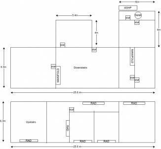
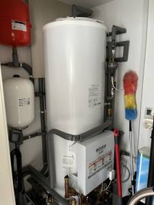
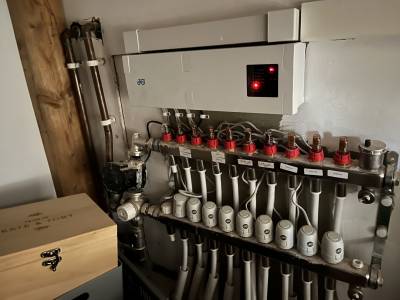
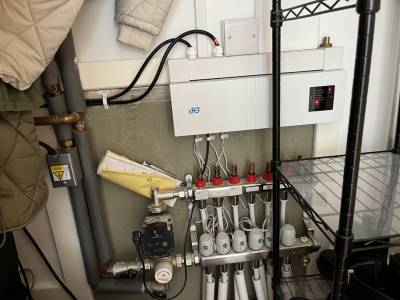
@derek-m Thank you for taking the time to help! I've attached a floor plan that shows the footprint of the house and location of the stats / manifolds. I've also attached photos of the tank / ftc and manifolds.
I have the paperwork relating to the EPC (which was incorrectly calcuated using 'mains gas' 🙄) - I think it contains heat loss calculations, is that what you're after?
As for the radiator sizing ill do that today and let you know the results...
@jamespa Thank you for taking the time to respond, much appreciated.
The argument for not using blending valves seems logical to me! As for the zone valves and sizing I've attached some pictures in my reply to Derek, perhaps that will help with identifying if 14kw is overkill...
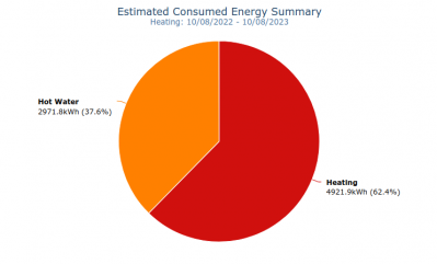
See attached screenshots from the mitsubishi app showing usage.
As for the hot water / ufh / pump ftc issue the engineer mentioned i dont think i fully understand! Is he right in saying that the manifolds should be wired back to the FTC? Running cable now would be impossible so is there such thing as a wireless relay that could be used?
@tobydeh Do you have your meter readings for the same period? Also is there a pie chart for delivered energy similar to the one for consumed?
Also I see you have rads upstairs which explains the need (perhaps) for blending valves as these probably run at a higher temp. Can you recall if these felt hot, warm or cool in winter and did they feel cooler in the shoulder season?
A quick comparison of the two bar charts suggests the cop might not be too bad in December and January but is really bad in the shoulder season, consistent with a well over specified unit controlled by thermostats not weather compensation.
4kW peak of solar PV since 2011; EV and a 1930s house which has been partially renovated to improve its efficiency. 7kW Vaillant heat pump.
@jamespa Unfortunately it only has a pie chart for consumed. I can find the meter usage for the entire period but I can't break it down my month.
The radiators upstairs are heavy column rads and are probably unsuitable for the system (its a long story i wont bore you with but basically i asked for lightweight immitation column rads made from aliminium and ended up with these hefty things). In the past they have not been hot to the touch but the Engineer was tinkering when he was here and they definitely felt hotter than they have done in the past...
The stats are not setup how I would like - from my limited knowledge im under the impression that the system should be setup using weather compensation and then the stats can only be used to 'limit' and never call for heat. Would that be possible to setup or would everything need re-wiring?
Before delving deeper could I ask how technical are you? I can then decide how much detail I need to provide.
I forgot to ask is your home semi-detached or detached?
-
Running my new Nibe ASHP efficiently
14 hours ago
-
New Mitsubishi Ecodan 11.2kW installation - L9 errors and maybe more
16 hours ago
-
Weather compensation- why you should use it
3 days ago
-
Rodents! A word of warning for heat pump owners
3 days ago
-
Where has Watson gone?
3 days ago
- 26 Forums
- 2,396 Topics
- 54.3 K Posts
- 276 Online
- 6,077 Members
Join Us!
Worth Watching
Latest Posts
-
RE: RDSAP10 effect on existing heat pump EPC rating?
@editor if possible please correct my reply above. In...
By Tim441 , 49 minutes ago
-

RE: Setback savings - fact or fiction?
No need to create a new thread, @sheriff-fatman. You do...
By Majordennisbloodnok , 8 hours ago
-

RE: Power outages and storms: A surprisingly good DNO experience
Well done to Scottish Power for doing a good job. Well ...
By Majordennisbloodnok , 9 hours ago
-
RE: Advice for a novice on Mitsubishi Ecodan 6kW
Fair point. The highest frequency of defrosts I'd seen...
By Sheriff Fatman , 10 hours ago
-

RE: Heatpunk Floor plan issues
It's usually the complete opposite... seldom that Safar...
By Mars , 10 hours ago
-
RE: Recommended home battery inverters + regulatory matters - help requested
I remember reading in some inverters. They mandate a se...
By Batpred , 11 hours ago
-

RE: Fan is clipping ice build up from the front of unit.
@majordennisbloodnok I’ll not go there thanks! Toodles.
By Toodles , 13 hours ago
-

RE: Running from backup generaor in powercut?
@majordennisbloodnok Back in the 80’ or 90’ we had a te...
By Toodles , 13 hours ago
-
RE: Running my new Nibe ASHP efficiently
I'm new to the forum. Did you get a reply to this last ...
By Mike @ Camelot , 14 hours ago
-

RE: ASHP Energy Consumption: Aira 12kW heat pump
@grantmethestrength MCS requirements for DHW capacity h...
By Toodles , 15 hours ago
-
RE: New Mitsubishi Ecodan 11.2kW installation - L9 errors and maybe more
Great to hear! I just figured this out a day or tw...
By anotherdaveuk , 16 hours ago
-
RE: Help me keep the faith with my air source heat pump installation
@adamk I'm observing my own system at low temperatures ...
By dr_dongle , 21 hours ago
-

RE: Free Ecoheat Heat Pump Install
@deltona Yes older houses are problematic like that, bu...
By bontwoody , 2 days ago
-
RE: Radiator sizing sanity check
As I mentioned early on the cost of supplying and fitti...
By JamesPa , 2 days ago
-
RE: Electricity price predictions
Great point, one of the key ones in my chat with Octopu...
By Batpred , 2 days ago
-

RE: New Fogstar 15.5kWh upright solution
Let me point out that there are many Chinese suppliers ...
By Transparent , 3 days ago
-

RE: Weather compensation- why you should use it
@majordennisbloodnok — The Two Ronnies Mastermind sketc...
By cathodeRay , 3 days ago
-
Just realised that this image of the cylinder cupboard ...
By Sheriff Fatman , 3 days ago
-

RE: Rodents! A word of warning for heat pump owners
Two thoughts: 1: Let's ask @david-s if Primary Pro in...
By Transparent , 3 days ago
-
RE: Solis S6-EH1P8K-L-PLUS – Why I Chose It and What I’ve Learned So Far
In the diagram below, I describe my understanding of th...
By Batpred , 3 days ago


