Discussion on buffer tanks and heat pumps
Hi All,
After a brief discussion on buffer tanks on another thread I though we could have a proper discussion here about them.
So will describe my setup below and then see what the forum thinks. Apologies for the long intro.
240m2 house over three floors. It’s a 1970 house built with concrete columns and cavity walls.
I recently completely renovated it so has underfloor in all areas. Insulation was improved and about 50% of the internal walls on the cavity walls were removed and rebuilt with 60mm of XPS insulations added.
16kW Daikin heat pump and Daikin HW cylinder. So everywhere was zoned for individual control, when its just my partner and I in the house about half is not really used so we leave that at 18 deg. The rest is heated to 21.
The house is in Spain so not as cold in the winter as in the UK but still needs heating from early Nov until March.
Heat loss calculations are a thing of mystery to Spanish plumbers sadly, I really tried but I think the estimate for the size of the heat pump was done on the back of a fag packet. I am reasonably confident it is oversized. I am using using weather compensation although neither the plumber or the Daikin rep who commissioned the system explained or I think even understood it!
So my issue is short cycling when only one or two zones are asking for heat.
I have seen the discussion about removing all zoning and I totally understand the logic but two points.
With varying levels of insulation then it would be hard to maintain a consistent temperature around the whole house.
With quite a lot of the house unused when we have no guests (unsurprisingly living in Spain guests can be quite common!) is it not better not to heat this to about 16 or 18 and save that energy?
With my situation would a buffer tank be a sensible addition?
If just say the study is asking for heat then the pump can start up to 4 times an hour. If I had say a 150ltr buffer than would that not reduce it to say twice an hour and allow the heat pump to run slower for longer.
I have read this page with interest.
https://blog.heatspring.com/2-pipe-versus-4-pipe-buffer-tank-configurations/
The layout in figure 4 seems to make a lot of sense to me.
Look forward to your thoughts, thankyou.
Adam
Assuming you’re not causing a low flow fault. It’s likely that the heat output of your emitters is too low for the minimum of the heat pump. As they’re unable to dissipate the heat your flow temp is probably going above what the setting hence the heat pump shuts off.
A buffer tank would increase the thermal mass of your system but it will cost you in terms of efficiency. There might be other benefits though in terms of hydraulic separation.
Hi Adam and Matt,
Thank you Adam for providing the link to the highly interesting article, and you are correct in that buffer tanks are an area that requires further investigation and discussion.
When I first started researching ASHP's and I saw schematics which included a buffer tank, I thought 'why on earth would they install something that could be a potential source of heat loss'. But then I was used to a gas fired heating system, which is designed to switch on and off as required to meet the heat demand.
Before delving into the inner mysteries of buffer tanks themselves, it may be best to look at the requirements of the full heating system, and the strengths and weaknesses of the component parts.
Heat Emitters.
Heat emitters, in one form or another, are required to transfer the heat energy from the central heating water, into the airspace within the property. The heat emitters themselves are not particularly bothered what the temperature of the central heating water is, provided that it provides sufficient heat energy to meet the heat demand. So as the ambient air temperature falls, the heat emitters would required warmer central heating water to be able to perform their task. As the ambient air temperature increases, the heat emitters would still be able to perform their task with central heating water still at the same temperature, but the flow would need to be regulated in some way to prevent indoor temperatures from rising above the desired level. So heat emitters have a minimum required water flow temperature for them to be able to perform their required task.
ASHP.
Close inspection of the data provided by ASHP manufacturers, reveals that for optimum efficiency, the water flow temperature needs to be kept as low as possible. So for best operation, an ASHP has a maximum water flow temperature, that meets the required heat demand.
So as you can see from the above, two of the primary elements of a heating system have conflicting requirements from the point of view of optimum operation and efficiency.
Probably the greatest factor with which an ASHP system has to cope, is the wide variation in operating conditions, from little or no heat demand in the Summer, to very large heat demand in the depths of Winter. Modern ASHP's have been designed to cope with this wide range of operating conditions, with the inclusion of inverter drives for the compressor, and I believe also for the fan and water pump. But as with any type of equipment there are maximum and minimum limits beyond which they cannot operate. Obviously the maximum heat demand determines the size of heat pump required for a particular property, taking into account the minimum anticipated ambient air temperature, the type and size of the heat emitters, and any other factors which affect the maximum heat demand.
Once a correctly sized heat pump has been selected, the manufacturers data sheets will also specify the minimum operating conditions under which the ASHP will operate consistently.
So under what circumstances may it be necessary to require a buffer tank to be installed within a heating system.
If the heat demand is always above the minimum heat output of the ASHP, then a correctly adjusted heating system would continue to run, providing a water flow temperature, that provides sufficient heat energy to match the heat demand required to maintain the desired indoor temperature. Of course, there are times, even during the same day, when the heat demand falls below the minimum heat output of the ASHP, so either the temperature within the property must be allowed to rise to increase the heat demand, or the heat pump must be stopped for a period of time. Heat pump manufacturers specified the acceptable frequency at which the on - off, or 'cycling' can occur.
In a heating system that contains a variations of controls such as zoning, thermostats, diverter valves and TRV's, the instantaneous heat demand and flow rate can vary considerably, from one small heat emitter being activated in a small room, to the whole system calling for heat energy at the same time. From an ASHP's point of view this is probably the worst case scenario, since it operates most efficiently when providing a constant supply of heat energy, at the lowest water flow temperature that meets demand. Continuous variations in heat demand, above and below the minimum heat output of the heat pump, could of course lead to frequent stopping and starting.
It would appear, particularly with the earlier types of ASHP's, that buffer tanks were incorporated within the design, to help smooth out the changes in heat demand and hence loading on the heat pump. The buffer tank providing a 'heat sink' (somewhere for any excess heat energy to go) rather than shutting down the heat pump prematurely. A buffer tank can also provide a 'heat source', to provide heat energy when the heat demand is low, rather than starting up and running the heat pump for a short period of time.
Personally, I don't think that there is a black and white answer to 'should a buffer tank be installed within a heating system or not'. In some cases it could be beneficial and improve the operation and efficiency, in other cases it may not do so.
Another thing to consider should a buffer tank be installed in a system, is its size, type and location. Not everyone may have the room to install even a small buffer tank, let alone a large one.
Having read through the article provide by Adam, I wonder if the overall heating system performance could be enhanced, by the installation of a large heat store, in the form of a basic hot water tank acting as a two pipe buffer tank. In this format an immersion heater could be installed, and powered by a solar PV system via a suitable power diverter. A solar thermal system could also provide heat energy via the heat coil located within the tank. If such a system were installed, it would help reduce the need for the heat pump to operate, when the heat demand in the property is low. It should also improve the overall system efficiency and help reduce energy consumption.
Heating system control and the design and use of buffer tanks are an area that I think one or more of the UK Universities should be researching. Maybe then we will have the answer to 'Buffer Tank or not'.
Hi Everyone,
To help research the 'buffer tank or not' dilemma, would any of the forum members be willing to check their systems and indicate whether they have a buffer tank installed or not. If you are not certain what to look for then just Google 'buffer tank'.
If you do have a buffer tank, it would be useful if you could provide as much detail as possible, manufacturer, model, size and type etc. It may then be possible to compare the operation of the various systems to see if there are any appreciable differences in performance.
Thanks in anticipation.
Retrofitted 11.2kw Mitsubishi Ecodan to new radiators commissioned November 2021.
14 x 500w Monocrystalline solar panels.
2 ESS Smile G3 10.1 batteries.
ESS Smile G3 5kw inverter.
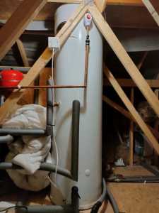
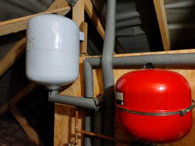
@derek-m our diagram shows a buffer tank. Although I'm not sure what it might look like
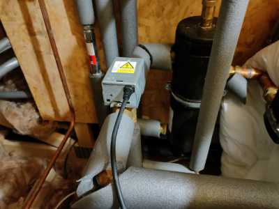
Some images above - ignore the duvet, I wrapped it round the pump to deaden the hummmm (as requested by the wife)
Hi Everyone,
I have just been reading in the Ecodan manual, that there is a minimum water capacity requirement for the primary circuit (the water that flows through the ASHP and around the central heating system).
If the capacity of the system is below the minimum required by the particular size of heat pump, the recommendation is that a buffer tank be installed. Obviously, installing a capacity vessel, as suggested by Brendon, would also increase the system capacity above the minimum specified.
There is also a maximum system capacity, above which the expansion vessel located within the ASHP would not be able to cope, and would probably require the installation of an external expansion vessel.
Whilst it does not answer the question of which is best, it does at least explain why your system may have a buffer tank installed.
Considering the above requirements, having zoning valves or TRV's will not effect the overall system capacity, but could vary the loading on the heat pump as they open and close.
The black cylinder looks like a low loss header as opposed to a buffer tank. It will give you hydraulic separation but without adding significantly to the overall capacity of the system.
Given your system is in the loft the heat pumps internal circulation pump may not have the required head at the required flow for your needs. Hence the additional circulation pump coming from low loss header, it will also ensure that adequate flow is maintained for your heat pump.
@mattengineer makes sense to me. It's a two storey house, so it's got to rise about 5-7m to get to the loft
- 27 Forums
- 2,495 Topics
- 57.8 K Posts
- 225 Online
- 6,220 Members
Join Us!
Worth Watching
Latest Posts
-

RE: Electricity price predictions
@transparent Triggered by the various commen...
By JamesPa , 8 minutes ago
-

RE: Solis inverters S6-EH1P: pros and cons and battery options
Just to wrap this up here for future readers: The S...
By Batpred , 38 minutes ago
-
RE: Struggling to get CoP above 3 with 6 kw Ecodan ASHP
Welcome to the forums.I assume that you're getting the ...
By Sheriff Fatman , 44 minutes ago
-

RE: What determines the SOC of a battery?
I agree. Fogstar confirmed that the Seplos BMS does ...
By Batpred , 1 hour ago
-
RE: Humidity, or lack thereof... is my heat pump making rooms drier?
I've found that generally the humidity in the house is ...
By IRMartini , 1 hour ago
-
RE: Say hello and introduce yourself
@editor @kev1964-irl This discussion might be best had ...
By GC61 , 2 hours ago
-

RE: Testing new controls/monitoring for Midea Clone ASHP
@benson — as @tasos suggests, plotting multiple variabl...
By cathodeRay , 5 hours ago
-

@painter26 — as @jamespa says, it's for filling and re-...
By cathodeRay , 6 hours ago
-

RE: Oversized 10.5kW Grant Aerona Heat Pump on Microbore Pipes and Undersized Rads
@uknick TBH if I were taking the floor up ...
By JamesPa , 17 hours ago
-

RE: Getting ready for export with a BESS
I would have not got it if it was that tight
By Batpred , 19 hours ago
-

RE: Setback savings - fact or fiction?
I also need to correct something I said by mistake earl...
By cathodeRay , 19 hours ago
-
RE: Need help maximising COP of 3.5kW Valiant Aerotherm heat pump
@judith thanks Judith. Confirmation appreciated. The ...
By DavidB , 22 hours ago
-

RE: Recommended home battery inverters + regulatory matters - help requested
That makes sense. I thought better to comment in this t...
By Batpred , 22 hours ago
-
Bosch CS5800i 7kW replacing Greenstar Junior 28i
My heat pump journey began a couple of years ago when I...
By Slartibartfast , 22 hours ago
-

RE: How to control DHW with Honeywell EvoHome on Trianco ActiveAir 5 kW ASHP
The last photo is defrost for sure (or cooling, but pre...
By JamesPa , 24 hours ago
-

RE: Plug and play solar. Thoughts?
Essentially, this just needed legislation. In Germany t...
By Batpred , 1 day ago
-
RE: A Smarter Smart Controller from Homely?
@toodles Intentional opening of any warranty “can of wo...
By Papahuhu , 1 day ago
-
RE: Safety update; RCBOs supplying inverters or storage batteries
Thanks @transparent Thankyou for your advic...
By Bash , 1 day ago
-
RE: Air source heat pump roll call – what heat pump brand and model do you have?
Forum Handle: Odd_LionManufacturer: SamsungModel: Samsu...
By Odd_Lion , 1 day ago
-
RE: Configuring third party dongle for Ecodan local control
Well, it was mentioned before in the early pos...
By F1p , 2 days ago
-

RE: DIY solar upgrade - Considering adding more panels
I know this is a bit old, but it made me wonder what co...
By Batpred , 2 days ago
-

RE: New Vaillant aroTherm Plus in black - When will it come to the UK?
@majordennisbloodnok Daikin, take note! (In fact, I hav...
By Toodles , 2 days ago
-

RE: Midea ASHP – how to set weather compensation
@mk4 — good work! First, I agree, no evidence of cycl...
By cathodeRay , 2 days ago


