How do you feel about using combustible ply inside a battery enclosure @misterb ?
You're 'pushing' the boundaries a bit with using Melamine to provide a level base for the cells.
But at least it's recommended for use in kitchens and can withstand a boiling pan being placed on it at 100degC
I very rarely have high currents passing through my LiFePO4 batteries.
I'm confident that they 'run cold' under normal operating conditions, which I classify as 100A import or export.
But I have had overheating due to other conditions
- a 125A-rated MCB (trip) which opened its contacts due to thermal overload at a steady current of only 80A
- a bolt connecting a 600A copper busbar to a micro-resistance being used for current measurement. Thermal cycling had loosened the thread
- a 6mm nut connecting a 25sq.mm cable, which I'd forgotten to check with the torque wrench when I'd changed a BMS
All of these items can also be found within your Seplos case. 😮
For this reason I generally use cementitious board if the sheet is going to actually be in contact with the cells.
And I keep plastic parts to a low-mass.
They will usually melt at around 200degC, but they'll be small enough parts not to cause a run-away fire.
The PVC tape I suggested would fall into that category, although I'd use a non-combustible tape if I had one to hand.
The problem with cementitious boards is that they are generally sold in large sheets (2.4 x 1.2m) and that they tend to be brittle.
It's great, provided you're not using it structurally.
The exception to this is Fermacell, which is a wall-board.
That can be used structurally... because I build walls using it (instead of plasterboard) in high-traffic areas. 👍
Save energy... recycle electrons!
the ply wasnt meant to be in contact and certainly not left in situ, it was potentially a way of stopping anything touching the terminal connections while assembling the top part ...
and whilst i obv wouldnt want an issue, the inverter, batteries etc are in an outside utility room far enough away from the house, if there ever was an issue as the fire loading isnt particularly large and wouldnt constitute a significant life threatening risk, if anything did happen.
everything can be isolated from within the house ...
thanks for your comments re overheating and i hadnt planned checks every now and again, but its certainly something i will consider AND i have just bought an double pole 100A circuit breaker to replace the single isolator i fitted originally (see, i do listen and take things on board LOL 👍 )
My batteries are also in an (unheated) plant-room.
I have four other doors to the outside,
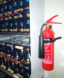
but I've also invested in a couple of these in case I make a mistake whilst actually working on the installation...
Save energy... recycle electrons!
Posted by: @transparentThermal cycling had loosened the thread
Quick question; what is the best practice around how frequently these bolts/nuts should be checked? Once a year? The connections can undergo many thermal cycles a day (turning oven on, showery weather, etc) Or should we be considering some sort of thread locking solution to prevent it working loose?
The question might be quick @chickenbig but the answer open-ended, both in time and depth of physics 🤔
May I remind readers here that I'm doing R&D.
So I 'experiment' with things which I wouldn't propose here as being 'good practice'.
As far as I can tell, the connections which we make to our battery cells, fuses BMS units and inverters don't work themselves loose due to thermal cycling.
Those which I've had to 'attend to' have been due to errors on my part, such as an improperly crimped terminal lug.
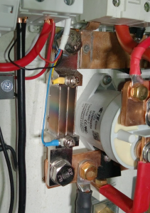
The bolts I referred to above are on a micro-resistance link which can be seen in this photo
This is an off-the-shelf shunt supplied by a reputable manufacturer in China, and I've used the stainless steel M10 bolts which it came with.
The shunt produces a 75mV drop across it at its maximum current rating of 300A.
That makes it 0.0025ohms (2.5mΩ or 2500μΩ) - hence the term 'micro-resistance'
and that means it produces 7.5W of power per 100A current.
You can see the visual effects of the heat which has built up during my tests, all of which are well below the rated 300A.
There is striated discolouration in the centre of the three copper-alloy blades which provide that resistance,
and the yellow sense-wire at the top has a small amount of black residue protruding from the heat-shrink sleeve where it joins the crimp connector.
That is almost certainly charred insulation from the yellow wire, which is specified for 80°C.
I had assumed that the large mass of copper bar to which the shunt was bolted would adequately dissipate the heat.
the lower busbar is 25x3mm (75²mm cross-sectional area)) and the upper one 25x4mm (100²mm).
But as the shunt heats up, the stainless steel bolt threads expand at a lower rate than the threads I've cut into the copper.
That increases thermal resistance where the shunt meets the copper bar, meaning that the shunt itself gets hotter.
There are two possible solutions which immediately present themselves:
- fit an M10 locknut where the bolt protrudes behind each busbar, thus clamping the ends of the shunt more securely to the copper
- replace the stainless steel bolts with a pair made of brass or copper
That doesn't directly answer your original question...
... but it needs addressing here because this thread has several contributors who are planning to link up multiple batteries, each of which might be expected to deliver 100A under normal operating conditions.
Save energy... recycle electrons!
As we are also mentioning inverters to use with the Mason boxes, and I kept on mentioning Sunsynk, I thought I would mention my current experience as one has been installed in a relative’s house.
- The inverter manual is pretty vague about key safety features such as earthing of the case using an external fixing (and makes no mention of the earth bar inside the case).
- Key workflows such as the pairing of logging stick and inverter to a “plant” do not document possible errors. This may be more of an “installer competence deficit”.
- Sunsynk are currently undergoing a cloud change where the world is being divided up into regions. This creates problems as I can have an account in region 2 which can not be connected to an inverter in region 1 … the name of the account does not make the namespace (I.e. region) obvious.
- The logging stick broadcasts an always-on Wi-Fi network with password ‘12345678’. Well, I say always on, but once it did stop broadcasting (or doing anything) until restart, I guess it had probably hung due to the intermittent internet connection (see next point).
- The inverter does not play nicely with (TP-link AV600) power-line Wi-Fi extenders when in “zero export” mode, but not when there is a surfeit of PV. Presumably the harmonics are bad when trying to clip the power exported to the grid.
- The touchscreen user interface does not have great labels, so with something like “Zero Export” activated it is still possible to export 5kW (if that is coming from solar). Naming things is hard, but 0 != 5000.
- I have found that some settings keep on getting reverted (“Use Timer” and “Prioritize Load”) after a few seconds or tens of seconds. This is in the absence of the logging stick (and so internet connectivity).
- I have also found that the charge/discharge schedule spontaneously gets strange entries added (to charge from grid and generator to 100%) when there is internet connectivity.
- It is not clear to me how or why export or import decisions are made; perhaps this is lack of knowledge on my part. For instance today I have had a situation where a 100% full pair of batteries (with 200A discharge enabled) was not used to power the house, despite having the “Priority Load” box ticked. Instead power was drawn from the grid.
That detailed feedback needs sending back to SunSynk.
They are very keen to establish a good reputation in the European market.
One question I raised with them resulted in a phone call from a senior engineering manager in South Africa - impressive!
They are aware of inconsistencies in installation practices and regulations between the countries they export to.
If you look at the installation diagrams, you'll see that there's a mixture of different wire colours being used(!)
That's why it's also difficult to specify the 'correct' way to provide an earth.
Here in the UK we have two different earthing arrangements for EV-chargers, for example.
So it's tricky for Sunsynk to write a definitive manual.
They really do need this level of feedback. In the long run it helps everyone.
Save energy... recycle electrons!
Posted by: @transparentThey are very keen to establish a good reputation in the European market.
For me the video on https://www.sunsynk.org/post/battery-bms-and-restart-shutdown-voltages says something deep about how the UI and core software interact. There exist 2 firmware versions on the device and one on the logging stick, so somehow communicate through an interface. The video (from 2020) states that startup and shutdown battery voltages can only be set when in non-lithium battery mode, but still should be set for lithium. It suggests the interaction is via a (super-)set of registers, only some of which are (modally) displayed but all of which can have an effect on the behavior. That is the UI software is a skin over the top of the MCU software (which is more carefully controlled as it appears to be specified for G98/G99/G100 approval), and displays a subset of active values.
I suspect that the lack of using battery power to support solar is a result of this hidden configuration since it stopped working after I tried limiting grid power (per G100 feature … although it was not password protected, unlike the G100 declaration).
Although trying to debug software can be an interesting activity, it is getting too close to actual work (and without the benefit of access to the source code, API documentation or monetary reward).
Posted by: @chickenbigmore carefully controlled as it appears to be specified for G98/G99/G100 approval
That depends on when SunSynk wrote that code.
A video from 2020 can't refer to inverter controls which will comply with later regulations.
Our UK regulations are not static; they evolve over time.
For example, you can read the latest G100 Issue 2, Amendment 2 regulations from the Electrical Networks Association
and note that this now applies to the import of electricity to charge off-grid storage batteries.
However, there is no matching form or application guidance yet available on the customer-facing website of my DNO. 🤔
This makes it very difficult for manufacturers, suppliers and installers of inverters which are designed to manage off-grid batteries.
I don't know of any such inverters which have been designed with a compliant Customer Export or Import Limitation Scheme (CLS)
because the customer could readily circumvent the import limitation by reconfiguring the inverter from an App or front-panel LCD menu system.
Nor do I yet know if the G100 Amendment 2 regulation is retrospective to sites where batteries existed from an earlier date.
It's possible that SunSynk are attempting to comply with the new G100 release by making changes to their control/management software in the cloud, without needing to re-flash the firmware within existing inverters.
But to do that they'd need to separate the world into different zones.
You don't want the European-based regulations being applied to Africa, China or Australia for example.
And that's what you've just complained about... because it isn't properly implemented.
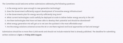
This is an issue which really needs raising with the House of Commons Select Committee on Energy.
They want to know if the UK statutory bodies and Government are sufficiently encouraging new technology which will help achieve Net Zero
Save energy... recycle electrons!
Update:
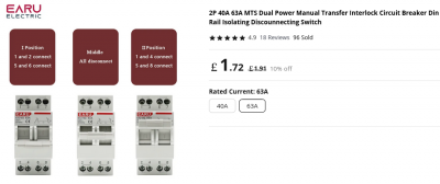
Earlier in this discussion @chickenbig and I were recommending to @misterb a manual transfer switch (MTS) and I posted a photo of a couple I have here.
I've now come across a much cheaper/smaller MTS from the Chinese Manufacturer Earu.
It too is double-pole, and thus switches the live and neutral simultaneously. That's important when using off-grid batteries.
Better still, it has a central position where both inputs are disconnected.
That provides reassurance that the switch really does offer Break-before-Make operation.
Save energy... recycle electrons!
Posted by: @chickenbigAs we are also mentioning inverters to use with the Mason boxes, and I kept on mentioning Sunsynk, I thought I would mention my current experience as one has been installed in a relative’s house.
I agree the instructions are pretty bad, and worse, not updated correctly over time I think (different screenshots vs reality). Did the inverter get installed by an approved Sunynk installer out of interest? I did my 5kW with my own electrician, but it does look like Sunsynk are making it hard for self installs by making it hard to contact/discuss anything with them - I haven't yet tried, but I need to about my new 3 Phase due to a problem setting it up as AC-coupled, and all postings on the web seem to suggest tech support is for installer not end use user only.
One other clarification of your points, are you accessing the inverter via the Sunsynk app, or directly on the display? I haven't got access to settings on the app as it's in end user access level at the moment and keep meaning to request upgrade to installer level.
I haven't had any issues with the Wifi install, or settings getting reverted, which is why I am checking if you are using the APP or direct. On the touchscreen you need to make sure you press OK each screen to save settings, otherwise it won't save.
Also - so we have a reference, what is the set up/use case for the inverter - does it have solar attached, or just battery? Will it be used on TOU? How is the inverter set up - with a grid and load connection, or just grid?
Posted by: @chickenbig
- It is not clear to me how or why export or import decisions are made; perhaps this is lack of knowledge on my part. For instance today I have had a situation where a 100% full pair of batteries (with 200A discharge enabled) was not used to power the house, despite having the “Priority Load” box ticked. Instead power was drawn from the grid.
The "system mode" screen is probably the most important, yet the manual description is very vague and hard to understand. There is confusing language, and inter-changable "Load" is used to mean the loads on the Grid connection, but also the meaning only the Load on the "essential Load" connection. I think, but not 100%, that the Priority Load means the "essential load" connection. I have it unticked on my system.
Posted by: @vaugisettings getting reverted
Part of the problem was that (unknown to me) the installer set up Octopus Agile integration with zero prices which seems to trigger the charge logic. Don’t quite know why zero prices do that for charge logic. Anyhow, this Octopus integration is only visible from the Connect app or web interface, and gets turned into the System Mode 1 schedule which is pushed to the inverter. So good luck to me trying to find that stuff on the inverter UI (and one has to think about whether there is a race condition in there). This does not explain why some other settings are reverted even when the inverter has no internet connection.
Posted by: @vaugiover time I think (different screenshots vs reality). Did the inverter get installed by an approved Sunynk installer out of interest?
I now see that they are not on the approved installer list … guess that is better than being on the not approved list.
Posted by: @vaugidoes it have solar attached, or just battery? Will it be used on TOU?
Solar and battery. Moving to Octopus Flux, if the smart meter works out in the sticks, so hopefully TOU.
The problem with discharging not happening turned out to be related to the charge voltages (float/absorbtion/equalization), but I got to that conclusion by fuzzing the configured values until it started taking energy from the batteries. There is no visibility about why a decision is made by the inverter.
- 27 Forums
- 2,495 Topics
- 57.8 K Posts
- 267 Online
- 6,220 Members
Join Us!
Worth Watching
Latest Posts
-
RE: Setback savings - fact or fiction?
@cathoderay The input power is largely determined by...
By RobS , 51 minutes ago
-

RE: Humidity, or lack thereof... is my heat pump making rooms drier?
@editor, this is now an example of greenwashing in the ...
By Majordennisbloodnok , 1 hour ago
-

RE: Electricity price predictions
@transparent Im impressed by all your work on this. ...
By JamesPa , 2 hours ago
-

RE: Solis inverters S6-EH1P: pros and cons and battery options
Just to wrap this up here for future readers: The S...
By Batpred , 3 hours ago
-
RE: Struggling to get CoP above 3 with 6 kw Ecodan ASHP
Welcome to the forums.I assume that you're getting the ...
By Sheriff Fatman , 3 hours ago
-

RE: What determines the SOC of a battery?
I agree. Fogstar confirmed that the Seplos BMS does ...
By Batpred , 3 hours ago
-
RE: Say hello and introduce yourself
@editor @kev1964-irl This discussion might be best had ...
By GC61 , 5 hours ago
-

RE: Testing new controls/monitoring for Midea Clone ASHP
@benson — as @tasos suggests, plotting multiple variabl...
By cathodeRay , 7 hours ago
-

@painter26 — as @jamespa says, it's for filling and re-...
By cathodeRay , 8 hours ago
-

RE: Oversized 10.5kW Grant Aerona Heat Pump on Microbore Pipes and Undersized Rads
@uknick TBH if I were taking the floor up ...
By JamesPa , 19 hours ago
-

RE: Getting ready for export with a BESS
I would have not got it if it was that tight
By Batpred , 21 hours ago
-
RE: Need help maximising COP of 3.5kW Valiant Aerotherm heat pump
@judith thanks Judith. Confirmation appreciated. The ...
By DavidB , 24 hours ago
-

RE: Recommended home battery inverters + regulatory matters - help requested
That makes sense. I thought better to comment in this t...
By Batpred , 1 day ago
-
Bosch CS5800i 7kW replacing Greenstar Junior 28i
My heat pump journey began a couple of years ago when I...
By Slartibartfast , 1 day ago
-

RE: How to control DHW with Honeywell EvoHome on Trianco ActiveAir 5 kW ASHP
The last photo is defrost for sure (or cooling, but pre...
By JamesPa , 1 day ago
-

RE: Plug and play solar. Thoughts?
Essentially, this just needed legislation. In Germany t...
By Batpred , 1 day ago
-
RE: A Smarter Smart Controller from Homely?
@toodles Intentional opening of any warranty “can of wo...
By Papahuhu , 1 day ago
-
RE: Safety update; RCBOs supplying inverters or storage batteries
Thanks @transparent Thankyou for your advic...
By Bash , 1 day ago
-
RE: Air source heat pump roll call – what heat pump brand and model do you have?
Forum Handle: Odd_LionManufacturer: SamsungModel: Samsu...
By Odd_Lion , 1 day ago
-
RE: Configuring third party dongle for Ecodan local control
Well, it was mentioned before in the early pos...
By F1p , 2 days ago
-

RE: DIY solar upgrade - Considering adding more panels
I know this is a bit old, but it made me wonder what co...
By Batpred , 2 days ago
-

RE: New Vaillant aroTherm Plus in black - When will it come to the UK?
@majordennisbloodnok Daikin, take note! (In fact, I hav...
By Toodles , 2 days ago
-

RE: Midea ASHP – how to set weather compensation
@mk4 — good work! First, I agree, no evidence of cycl...
By cathodeRay , 2 days ago


