@vaugi Yes those Mersen isolators are what I would go for (or else the Jean Mueller NH00 isolators which look to have better lug protection ... but do not buy the Jean Mueller NH00 fuses as they are generally not DC rated). 35mm2 cable sounds good to me.
The lug protection was the downside - you can get shrouds for the bigger ones, but Bimble didn't stock them for this size. I tried originally to go with the Jean Mueller ones but found they were either not stocked in the bigger size (for 160A) or quite a bit more expensive, perhaps stock has improved. In the end as one side is butt up against 100mm plastic trunking, and it's in a garage out of the way of small hands I thought this would suffice.
At a nominal 50v battery voltage, you would expect a 5kW inverter to draw 100A max.
But that assumes the current is steady. In reality, most loads will cause the inverter to have a switch-on surge, which is why the Sunsynk spec says 120A.
A fuse is usually sized to protect the cable to which it connects. Ie the fuse-link blows before the cable overheats in the situation where there is a fault (short-circuit).
That's a somewhat different concept to a DC-trip, which opens the contacts when you draw more current than is specified under normal (non-fault) operating conditions.
For each 5kW device (battery BMS or inverter) I tend to use a 125A DC trip and a Type-T fuse between 160-250A.
I can then safely connect these using 25mm² thin-wall (battery) wire, which is rated 170A max (continuous).
Save energy... recycle electrons!
ok, lots for me to consider and resolve then - bear with me as i am trying to type on the laptop, then go to my phone to add the photos !
the ct clamps are wired through an exterior rated ethernet cable, i used two cables, one for each CT clamp. the run of the cables around 4/5m in total. i tried to keep them separate to mains cables, which is why they were ran through conduits.
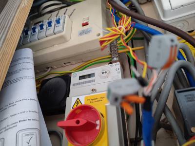
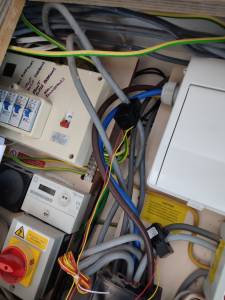
The white box with the cover is the feed to the inverter - its a consumer unit feeding ONLY the inverter. The cable from this to the inverter is 6mm armoured cable.
The wylex box on the far right contains fuses to the PV system which weve had for about 7 years now
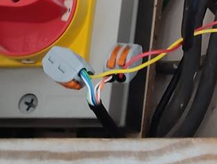
The mulitple ethernet cables are terminated in crimped connectors joining them together, they are not loosely held by the wago connectors. the wires to the CT clamps are also crimped as can be seen by the photograph below. i intended tidying all the wires up and reducing their length when everything is up and running,
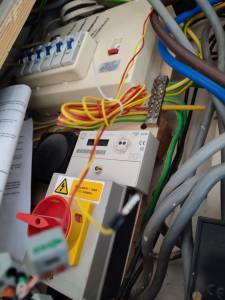
The red breaker near the inverter is placed high, i accept it should have been lower, but im sure its accessible by me and and any fire service personnel (though having spent almost 32 years in the fire brigade i am not as confident as you are that they would know what the hell it was ll for, let alone how to turn it off. if we ever wanted power isolating we pulled the main fuse using special rubber gloves !)
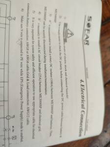
The Dc breaker to the battery is rated at 100Amps as per the sofar instructions and no, it isnt double pole and wasnt asked for either in the instructions. happy to change that on your recommendations, but im sure that isnt causing the issue. the cable size !S 16mm, Sofar recommend AWG6 or AWG8, which, after looking on line are 16mm and 10mm respectively. i chose to go for the bigger size.
Thanks for everyone responding and offering good advice on how perhaps i should 'improve' the elements of the system, but would any of those stop it working as it should? i will make some if not all of the suggested changes when its up and running, as i dont want to add potentially other elements into the equation at this point.
At the moment i am thinking its an issue with the ct clamp on the 'power' side not the PV side. next test will be to swap them over at the connections to the inverter. DOH ! I can just disconnect them at the 'sharp end' and swap them !!
ive spent the last ten minutes or so changing things around
i moved one of the CT clamps onto a different wire as shown on the next photo
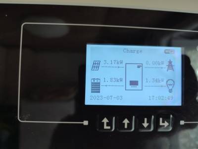
and on the following photo is now the reading on the inverter ..
Which is more of what I would expect. Could the solution have been that simple, or have I missed something?
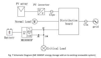
There should not be a CT clamp around the cable to the inverter; it knows how much current it is pushing out. There needs to be a CT clamp around the live wire going to the electricity meter as well as one around the wire going to the existing PV inverter (which looks to be correct).
The CT clamp cable itself needs to be correctly prepared to reduce the noise. Unfortunately your latest photos do not show which ethernet cable wires are used to convey the signal back to the Sofar box; I hope that only a single twisted pair is used.
I feel that some labelling on the various boxes would help with understanding, both for us on the forum as well as anyone else who needs to look at it. Whether this is a functional issue or not is, of course, up for debate.
Posted by: @chickenbigThere should not be a CT clamp around the cable to the inverter; it knows how much current it is pushing out.
Erm... that CT clamp is an input to the MP 3000-SE (Sofar's battery storage controller) rather than the pre-existing PV inverter.
According to the manual, it should be there.
I have yet to understand why the 3000-SE has two further CT inputs which are unused. Let's come back to that later if we need to.
Posted by: @chickenbigyour latest photos do not show which ethernet cable wires are used to convey the signal back to the Sofar box; I hope that only a single twisted pair is used.
I've zoomed in and had a closer look at an earlier photo.
This doesn't appear to be correct.
It looks like Orange/Org-Wht and Brown/Brn-Wht twisted pairs are connected to the Wago block with the red wire.
Each CT clamp needs to have one twisted-pair connecting it right back to the MP 3000-SP.
By that we mean that the red/yellow wires should be twisted together, and then connected to one of the four twisted-pairs in the ethernet cable.
Save energy... recycle electrons!
Thanks. They are two pairs of twisted wires (4 in total), I assume by your comment that I need to change them to single pairs for each connection
Your suggestion for things to be labelled is a good suggestion, I hadn't thought of doing that but it makes perfect sense (as do most of the other comments and suggestions from other contributors) over time I would prob have forgotten what was what, something I am encountering more and more at my age.!!
Thanks again for your help !
Rotary switches, and their use by the Fire Brigade
Posted by: @misterbif we ever wanted power isolating we pulled the main fuse using special rubber gloves !)
Well that's no good in a house that not only has storage batteries, but also a battery controller with an integral inverter which goes live at 240v AC when the main fuse is pulled 😣
Do you still have contacts amongst serving personnel?
If so, can you please check what procedure they use when entering a house that has such red/yellow rotary isolators?
Save energy... recycle electrons!
Posted by: @misterbI assume by your comment that I need to change them to single pairs for each connection
I think analog electronics is difficult; capacitance or noise from other wires makes things just a bit more difficult. Getting things to balance is important when all the stray kWh add up.
Posted by: @misterbCould the solution have been that simple,
It would be good to visually confirm that the clamp is around the correct wire, the live wire between the meter (or isolator) and Henley blocks. I would expect the inverter to do some maths to determine the non-self load (e.g. when charging from the mains it subtracts that from the CT clamp's measurement) so although things may look like they are currently working it may not quite be the case under all conditions,
Posted by: @transparentRotary switches, and their use by the Fire Brigade
Posted by: @misterbif we ever wanted power isolating we pulled the main fuse using special rubber gloves !)
Well that's no good in a house that not only has storage batteries, but also a battery controller with an integral inverter which goes live at 240v AC when the main fuse is pulled 😣
Do you still have contacts amongst serving personnel?
If so, can you please check what procedure they use when entering a house that has such red/yellow rotary isolators?
How would they know about any red,/yellow isolators if the house is full of smoke?
It's a nightmare scenario expecting or thinking that every firefighter, whether whole time or part time, knows every risk in every scenario at least very property or building. They depend very much on someone to advise them at the scene. The scenario re pulling the main fuse is a very rare occurrence and isn't done every time there is an incident, it's only where the power can't be isolated AND it needs to be!
Home storage batteries providing emergency power is probably something that hasnt been subject to an operational procedure being formulated. However if you have recognised you may have a system that could injure someone if the main fuse was pulled or even a power cut occurs then I will leave it to your conscience in how you should deal with it.
Posted by: @misterbHome storage batteries providing emergency power is probably something that hasnt been subject to an operational procedure being formulated.
I'm disappointed if that's the case.
The fitting of red/yellow rotary switches has been a requirement for houses with renewable generation/storage for over two decades.
Actually, there is no regulation which requires that they be fitted for off-grid storage systems, but I can't recall seeing one without a rotary switch for several years now.
We still tend to fit them, even if not a legal requirement. It's common sense to have them for use in emergencies... which obviously includes those attended by the fire brigade.
I do communicate with engineers who write such specifications, and I wonder if this would be a good moment to better assist the emergency services.
The UK is about to experience a major increase in the installation of domestic battery storage.
There is further signage which could be implemented if fire personnel wished to have it.
The design of those rotary switches could also be enhanced to have reflective bezels, for example,
and the height above floor level could also be stipulated.
Save energy... recycle electrons!
- 27 Forums
- 2,495 Topics
- 57.8 K Posts
- 395 Online
- 6,220 Members
Join Us!
Worth Watching
Latest Posts
-
RE: What determines the SOC of a battery?
@batpred I didn't write the Seplos BMS software, I a...
By Bash , 22 minutes ago
-

RE: Electricity price predictions
Sorry to derail this thread ‘slightly?’ but back to the...
By Toodles , 31 minutes ago
-

RE: Humidity, or lack thereof... is my heat pump making rooms drier?
Without knowing it, @andrewj, you've laid down the gaun...
By Majordennisbloodnok , 51 minutes ago
-
RE: Testing new controls/monitoring for Midea Clone ASHP
@tasos and @cathoderay thanks. I have some history grap...
By benson , 55 minutes ago
-

I am having my existing heat pump changed to a Vaillant...
By trebor12345 , 1 hour ago
-
Our Experience installing a heat pump into a Grade 2 Listed stone house
First want to thank everybody who has contributed to th...
By Travellingwave , 2 hours ago
-
RE: Setback savings - fact or fiction?
@cathoderay The input power is largely determined by...
By RobS , 3 hours ago
-

RE: Solis inverters S6-EH1P: pros and cons and battery options
Just to wrap this up here for future readers: The S...
By Batpred , 5 hours ago
-
RE: Struggling to get CoP above 3 with 6 kw Ecodan ASHP
Welcome to the forums.I assume that you're getting the ...
By Sheriff Fatman , 5 hours ago
-
RE: Say hello and introduce yourself
@editor @kev1964-irl This discussion might be best had ...
By GC61 , 6 hours ago
-

@painter26 — as @jamespa says, it's for filling and re-...
By cathodeRay , 10 hours ago
-

RE: Oversized 10.5kW Grant Aerona Heat Pump on Microbore Pipes and Undersized Rads
@uknick TBH if I were taking the floor up ...
By JamesPa , 21 hours ago
-

RE: Getting ready for export with a BESS
I would have not got it if it was that tight
By Batpred , 22 hours ago
-
RE: Need help maximising COP of 3.5kW Valiant Aerotherm heat pump
@judith thanks Judith. Confirmation appreciated. The ...
By DavidB , 1 day ago
-

RE: Recommended home battery inverters + regulatory matters - help requested
That makes sense. I thought better to comment in this t...
By Batpred , 1 day ago
-
Bosch CS5800i 7kW replacing Greenstar Junior 28i
My heat pump journey began a couple of years ago when I...
By Slartibartfast , 1 day ago
-

RE: How to control DHW with Honeywell EvoHome on Trianco ActiveAir 5 kW ASHP
The last photo is defrost for sure (or cooling, but pre...
By JamesPa , 1 day ago
-

RE: Plug and play solar. Thoughts?
Essentially, this just needed legislation. In Germany t...
By Batpred , 1 day ago
-
RE: A Smarter Smart Controller from Homely?
@toodles Intentional opening of any warranty “can of wo...
By Papahuhu , 1 day ago
-
RE: Safety update; RCBOs supplying inverters or storage batteries
Thanks @transparent Thankyou for your advic...
By Bash , 1 day ago
-
RE: Air source heat pump roll call – what heat pump brand and model do you have?
Forum Handle: Odd_LionManufacturer: SamsungModel: Samsu...
By Odd_Lion , 1 day ago
-
RE: Configuring third party dongle for Ecodan local control
Well, it was mentioned before in the early pos...
By F1p , 2 days ago
-

RE: DIY solar upgrade - Considering adding more panels
I know this is a bit old, but it made me wonder what co...
By Batpred , 2 days ago

