thanks, the grid port and load port refer to the Emergeny power supply (load port) which isnt connected or operative in the function settings, its referred to as the EPS
im not sure what you mean by concept of installation? i will try to do a quick sketch of the layout but its identical (as far as i can tell) from the layout shown in the manual
PS - thanks for sticking with me, it must be frustrating when dealing with a numpty like me LOL
Posted by: @misterbwhich isnt connected
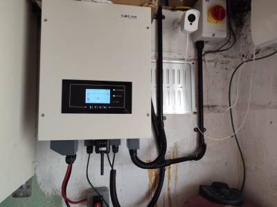
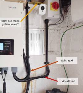
It was just your picture of the inverter shows to set of flexible cable trunking connecting to the right had side of the unit. I could not quite make out whether there was a wire coming out of the trunking which goes vertically up the RHS.
I agree with @chickenbig that we need more information on what's connected to the underside of the 3000-SE unit. Another photo perhaps?
There also appears to be a cardboard box on top, which won't be helping with the required airflow past the heat dissipation radiators!
Save energy... recycle electrons!
Posted by: @chickenbigPosted by: @misterbwhich isnt connected
It was just your picture of the inverter shows to set of flexible cable trunking connecting to the right had side of the unit. I could not quite make out whether there was a wire coming out of the trunking which goes vertically up the RHS.
i installed the trunking while i was doing a first fix and attaching everything to the wall, ready for the electrician, thanks for spotting it tand pointing it out though, shows you care ( ❤️ )
Re the cardboard box, you're right it needs moving. It's actually a Seplos 16s BMS with LCD screen that I originally bought last year to build my own battery, but it's not needed ..... Well not by me anyway !
The cables on the left are to/from the battery.
Next one (for m the left) is the Can communication cable between the battery and inverter as supplied by Sofar
Then the two CT Cables with the WiFi module in front of them and finally the incoming power supply cable.
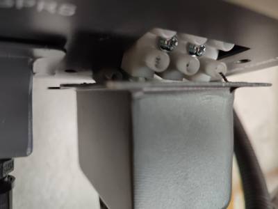
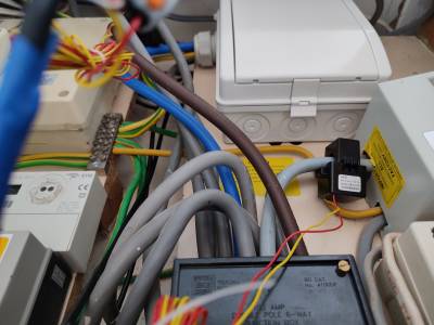
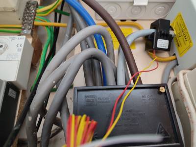
This next three photos are of the CT connections to the cables the cables from both the solar output and from the feed to the inverter both go into the same connector, the brown box thingy. Does that mean they are both effectively connected to each other, could that be the issue. The CT Cables are connected in the correct orientation as I colour coded them when installing the cables
Posted by: @misterb
-- Attachment is not available --
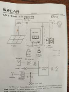
Above is the setup from the manual that the electrician followed
Any chance of photos of the CT clamps and the cables which go back to the Sofar inverter (in particular is ethernet cable used, how long the cable run is and whether the signal cables run at a distance from mains wires)? Is the CT clamp on the PV inverter showing the correct power generated? We have established that the CT clamp on the total house load is incorrect, haven't we?
Posted by: @misterbthe brown box thingy
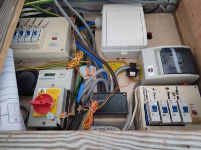
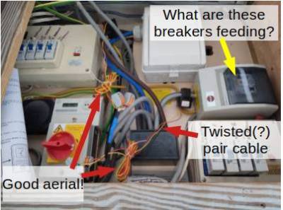
So your various consumer units are fed off these Henley Blocks. What does the white box at the top (with the cover closed) contain? And what is the Wylex box in the middle right contain?
In terms of wiring the CT clamps, the excessively long unshielded cable between the clamp and the ethernet cable is a little concerning (and probably should have been cut to length). More concerning is how multiple constituent ethernet wires are stuffed into a single wago terminal; I don't think that will help with getting a good signal back to the ME3000SP.
Having seen the photos, I too have a plethora of questions!
Why is the red/yellow "emergency breaker" placed so high up and to the right?
This is what you or the fire-brigade need to get to when things go wrong!
Save energy... recycle electrons!
Posted by: @transparentWhy is the red/yellow "emergency breaker" placed so high up and to the right?
I also wonder about the battery isolation. From the photo is not clear, but from the dangle of the cables I think it breaks just the positive wire. Note that I had trouble finding a reasonably priced DC rated two pole isolator (at least not in the > 100A range).
I too don't like the look of that breaker on the Battery wires. We discussed adequately-sized DC breakers earlier on this topic. You can buy them on eBay or Amazon but note that some are directly shipped from China.
Even so, those battery cables look like they're too thin in the photo.
For a Seplos Mason box I would expect them to be 25mm² but they look like 16mm² which can only carry 110A max. The cable capacity must always be well clear of the breaker's tripping-current.
Save energy... recycle electrons!
Posted by: @chickenbigI also wonder about the battery isolation. From the photo is not clear, but from the dangle of the cables I think it breaks just the positive wire. Note that I had trouble finding a reasonably priced DC rated two pole isolator (at least not in the > 100A range).
Do I understand it correctly, that the DC rated isolator should be sized based on the power of the inverter? My Sunsynk 5kW inverter has a max of 120A, so I used one of these Mersen NH00 with 160A fuses:
https://www.bimblesolar.com/DC-fused-disconnect-2pole
On advice from the Sunsynk manually I used 35mm2 tri rated cable for the inverter to isolator, the Seplos I ordered came with 50mm2 cables.
- 26 Forums
- 2,158 Topics
- 47.4 K Posts
- 56 Online
- 5,736 Members
Join Us!
Podcast Picks
Latest Posts
-
RE: 300 Liter Tank - Do I have to heat it all?
I do not think that a 300l cylinder is too big for a tw...
By jamespetts , 29 minutes ago
-
RE: Heat Pump SCOPs – The Truth Might Not Be What You Think
Is that heat loss, or maximum output of the ASHP? Unde...
By Scalextrix , 17 hours ago
-
RE: Mitsubishi Ecodan 11kw Defrosting Issue.
@morgan Fully agree with you. It shouldn't be the homeo...
By HCas , 18 hours ago
-
RE: Solar Thermal DHW and ASHP
@judith That makes sense to me! If I was in @alex_n '...
By HCas , 19 hours ago
-
RE: Vaillant aroTherm Plus 10kW thoughts?
Good unit. And the 10 kW is the same as the 12 kW I ...
By HCas , 19 hours ago
-

RE: A Customer's Lessons Learnt from a Heat Pump Installation in a Large House
@judith thanks for your suggestions. Starting from col...
By GrahamF , 22 hours ago
-
RE: Inventor (Midea) Heat Pump short cycling advice
I switched to "fan coil mode" to be able to set water t...
By immunity , 1 day ago
-
RE: DESNZ doing a survey which asks the right questions!
Without a survey their only source of data is probably ...
By JamesPa , 1 day ago
-
RE: Can you help with our research: solar panels, EV chargers, home batteries, heat pumps?
Just done your survey!
By Judith , 2 days ago
-
RE: Failing heat pump system - seeking thoughts on a rebuild
@cleardene-ashp just thinking about your issues here. Y...
By Judith , 2 days ago
-
RE: Midea ASHP – how to set weather compensation
@cathoderay OK let's wait and see, it sounds an interes...
By Tasos , 2 days ago
-

RE: What is the Heat Geek Guarantee?
@judith, I’m with you on Heat Geek, but there really do...
By Mars , 2 days ago
-
RE: Electricity price predictions
Community energy installations are a great idea, but th...
By Scalextrix , 3 days ago
-
RE: New Vaillant aroTherm Plus in black - When will it come to the UK?
Ooh, heat pumps in neon blue wrap 🤣 🤣 &...
By Old_Scientist , 3 days ago
-

@profzarkov Good to know in case it ever happens to me...
By bontwoody , 4 days ago
-
RE: Are Octopuses Slowing Consumer Adoption of Heat Pumps?
I mean, is this surprising? The local installers in my ...
By Alex , 4 days ago
-

@old_scientist sorry, I should have made it clear that ...
By GrahamF , 4 days ago
-
RE: Boiling Mad: Exposing Radiatorgate
Hi @Rob, I’d be more than happy to contribute. I have ...
By DREI , 4 days ago

