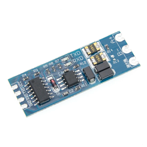
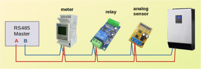
Or - to keep things even more simple - use this serial to RS485 adaptor module at £4 from Amazon
and about one-third of that price from AliExpress.
Save energy... recycle electrons!
Posted by: @transparentPlease allow me to dive in here!
I'm very glad you did. Thank you.
I've been communicating with Growatt inverters now for about a year, and I support the recommendation from @derek-m that you should use Modbus.
It's the most direct method to talk directly to the configuration registers and receive data in return.
The other methods are more tricky because of the network layers, and the fact that I suspect your inverter model is using two processor internally.
It's at this point that I think I need to do a bit of regrounding as to my understanding.
I'm well aware that Modbus is just a protocol, and I'm comfortable with it as such. However, I also know that before I can talk with something - in this case my inverter - there needs to be a device connected to the inverter, a device connected to my PC (or HA server or whatever) and a bit of physical or virtual wire between the two - a medium over which I can talk modbus. Owing to my IT experience to date, the talking bit doesn't fill me with significant concern - at least not yet. However, I'm still rather in the dark about what the inverter-end device needs to be, particularly bearing in mind that as far as I can see the inverter itself only has one free USB slot (that probably needs to be kept free) and one available RS232 serial port that is already taken by the wifi module. I guess the big question at this point is, knowing what I have detailed is the current setup with the inverter, if you were in my position what hardware if any would you get initially and how would you physically connect it? If you feel no extra hardware is necessary, how would you propose to physically communicate with the inverter?
[Inverters with two processors require two files to be transferred when attempting a firmware upgrade]
I'm kind of hoping I don't have to do any firmware upgrading, but even if I do that is probably a discussion for another point.
Having said that, in my experience the response of Growatt's inverters to any commands sent to it is unreliable.
The SPF-series which I use, is oriented such that its focus is on keeping the load supplied.
It isn't straightforward to configure it such that you specify when it should charge the battery from the grid, especially when PV panels are also alive and supplying charge.
Those commands are battery-focused.The internal clocks are useless in this regard.
You will need to leave them unset, and send timed commands over Modbus from your PC.
That is very interesting and might well be why the web site's configuration page keeps giving "set parameter failure" error messages when I do something simple like set the time. I think my first step after successfully setting up a means of communication is going to be simply to monitor so I can get used to manipulating traffic that doesn't affect anything. Hopefully I can start getting a feel for the inverter too, such as you already have.
It is quite likely that you will need to use a relay to decouple the PV input(s) from your inverter during daylight if you wish to take advantage of Agile plunge pricing.
That's not difficult to achieve and I can tell you which relay to use if you need it.You might find that there are occasions when the inverter doesn't cease to charge from the grid when the plunge-pricing period ends!
I've had this several times, and I've found no other method except a full re-start of the inverter.
For the SPF-5000 series, an inverter reset requires that it be connected only to the battery.
The grid-input and PV-input must be isolated when the re-start occurs.
It may be different for the SPH5000 of course.
Hmmm. Certainly food for thought once I'm up and running. To be frank, I'm well aware that Growatt as a company churn out workable but not necessarily premium products and that there are definitely metaphorical ragged edges to be seen on closer inspection.
Finally, until I read this thread and checked the specs for the SPH5000 I hadn't been aware that it was permissable in the UK to use a Growatt inverter which offers both
- export to the grid
- EPS (emergency) 240v AC output when there is a power-cut
I thought only Sunsync had received such approval.
I'd be delighted if you prove me wrong.
But let's sound a warning here, that there are inherent dangers in having a grid-tied inverter operating when the an outage is in progress.It means that the EPS output can either use the grid to synchronise itself with 50Hz, or it can be supplied with 50Hz reference frequency from an internal oscillator.
Personally I don't like having such a feature.
But if you are going to have mains appliances in the house connected to both the standard 240c AC inverter output connector and the EPS connector, then you should be very careful to use double-pole switches/trips/contactors. Keep the neutral wires separate!Anyone else reading this - please take note!
I certainly initially wanted to be able to keep power running from the battery in the event of a power cut but I dropped that from our wish list as soon as I saw just how quickly the ASHP would drain the battery anyway. With the setup we have, if there is a power cut then the inverter is not doing anything fancy for us and so we sit in the dark just as much as our neighbours.
Thanks for your help
105 m2 bungalow in South East England
Mitsubishi Ecodan 8.5 kW air source heat pump
18 x 360W solar panels
1 x 6 kW GroWatt battery and SPH5000 inverter
1 x Myenergi Zappi
1 x VW ID3
Raised beds for home-grown veg and chickens for eggs
"Semper in excretia; sumus solum profundum variat"
Posted by: @derek-mOne way to establish a connection from a computer to the inverter is by using the following:-
Is this what you had in mind?
Quite possibly, @derek-m.
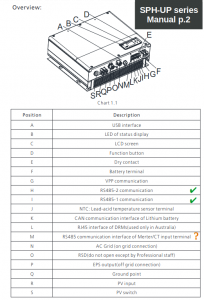
I can obviously see the network side easily enough, but I can't immediately see how I would connect it to the inverter. The documentation suggests there is an RS485 interface under the waterproof cover, but that is apparently for communication between the inverter and the battery and in any case is an RJ45 socket.
105 m2 bungalow in South East England
Mitsubishi Ecodan 8.5 kW air source heat pump
18 x 360W solar panels
1 x 6 kW GroWatt battery and SPH5000 inverter
1 x Myenergi Zappi
1 x VW ID3
Raised beds for home-grown veg and chickens for eggs
"Semper in excretia; sumus solum profundum variat"
Posted by: @transparentOr - to keep things even more simple - use this serial to RS485 adaptor module at £4 from Amazon
and about one-third of that price from AliExpress.-- Attachment is not available --
As with the probably more familiar looking (to me at least) device @derek-m suggested, I'm looking at that circuit board and scratching my head as to how it would connect to stuff. I think I might need a bit of a crash course in attaching plugs and sockets.
105 m2 bungalow in South East England
Mitsubishi Ecodan 8.5 kW air source heat pump
18 x 360W solar panels
1 x 6 kW GroWatt battery and SPH5000 inverter
1 x Myenergi Zappi
1 x VW ID3
Raised beds for home-grown veg and chickens for eggs
"Semper in excretia; sumus solum profundum variat"
So let me clarify...
The simplest strategy is to use Modbus commands over RS485.
The manual indicates at least two such ports are available for you to use
The internal processor which handles these data interfaces has a limited number of serial ports available.
Where you may connect will depend on what communications port is already deployed for your Growatt Battery.
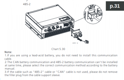
Look at the notes at the foot of page-31
The manual is assuming that you're going to use a Growatt-supplied RS485 cable.
Unhelpfully they have omitted the diagram for which wires you need to use if you make up your own cable!
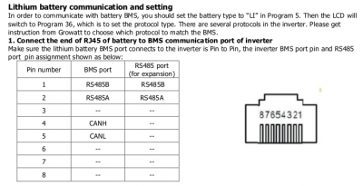
However, on other Growatt inverters they use an RJ45 connector (the same 8-pin plug as used for Ethernet) and pins 1& 2
Shall we assume that they've kept to this 'standard' throughout their range?
Save energy... recycle electrons!
To save you flitting all over the place, let me re-post here a basic introduction to Modbus over RS485
RS485 is a serial protocol which runs over a pair of wires, A and B
On a workbench I can use loose wires, but when installing devices I use a twisted-pair cable.
It can run to more than a kilometer across an entire industrial plant.
There may also be an earth wire connection.
It isn't mandatory. Sometimes a device manufacturer suggests it gets used for safety reasons.
It depends what devices you're connecting together, and whether the RS485 connections are opto-isolated.
There is one Master device, which is usually a computer.
Slave devices can be a meter, relays, signal acquisition modules or entire inverters.
Each 'slave' device must have a unique ID from 0 to 254.
That is set either by using pins/jumpers/switches or by sending it a Modbus command.
You also define the communications speed (baud rate).
It is sometimes the case that a particular slave device may only use a narrow range of IDs, such as 0-31.
It can also be the case that a device doesn't allow you to change its preset baud rate.
However, RS485 is very tolerant of that.
You can actually set the baud rate at the Master end, talk to one device, then change the speed again and talk to the rest of the modules!
There is no defined connector for using Modbus.
Each manufacturer makes up their own mind and then tells you what the pins do in the manual.
Save energy... recycle electrons!
@majordennisbloodnok - I think your problem is generically the same problem that I had, how to make a working physical connection to a modbus device, in my case an ASHP, in your case an inverter. I suspect both the principles and practice are identical, the only differences being in fine detail eg terminal labelling.
Once I had got my head round it, it turns out it is simple. It goes like this:
1. Use a modbus RTU RS485 wired connection. Modbus over IP/wifi or whatever just introduces pointless complexity (even if you are familiar with networks, why faff about with IP addresses when all you need is a two core wire?). Modbus is just another serial interface, you can think of it being like using a USB (another serial interface) connection, but it is more suited to connecting computers and devices. As others have said, it works on a one master one or more slaves basis, all daisy chained together, one after the other. I currently have master <=> room temp sensor <=> heat pump.
2. The wire I use is shielded twisted pair cat 5e network cable. It's fiddly to work with, AWG 26 I think, ie very thin wires, but it can be done. All the connections are screw down in some shape of form (no more complicated than wiring a mains plug, just a bit more fiddly).
3. Your computer/whatever does not understand RS485, but it does understand USB, and you can get a cheap two way RS485 to USB converter. There are plenty on ebay.
4. Modbus RTU over RS485 is, as noted, a two wire connection (+/- earth, I used a spare wire in the cat5e cable to make an earth connection). You are doing nothing more than the equivalent of wiring up an old fashioned door bell. Normally the two terminals are labelled A+ and B-, and you connect each to its own, ie A+ to A+, B- to B-. Sometimes (my heat pump is a case in point) the terminals are labelled differently on a proprietary device, eg the A+ terminal is labelled H2, and the B- terminal is labelled H1. The alternative labels, if used, are usually easy enough to identify from the manuals. Just make the connections, and finally add the 120 ohm terminal resistor (as detailed above).
5. That's it, you now have a physical modbus connection.
6. It is a truth, though not necessarily universally acknowledged, that a man in want of his sanity does not willingly get involved with Home Assistant. That said, if you want to use it, please do so. My primary connection is instead managed in python using the minimalmodbus module, which can read and write to modbus registers. The python code then logs the read data to csv files, which I can then chart and plot to my hearts content. If you know the basics of coding, it is not complicated. Before too long I will be posting more details on this, but I need to wait for the heating season to start as I have a final few checks to do before going public with the specific details of my system. In the fullness of time I hope to be able to set as well as get register values, ie control as well as monitor the system. I have already established this can be done (see posts passim), I just need to add the necessary control logic, the aim being to achieve an adaptive (to demand) weather compensation curve.
Midea 14kW (for now...) ASHP heating both building and DHW
A bit if a delay in replying here, since I still haven’t had the chance to get to the inverter and check whether the battery is connected via the CAN slot or the RS485 slot.
Nonetheless, from what you’re saying, @transparent, if the RS485 slot is free then I can simply run a network cable from there straight inside and it’s all ready sealed weather-wise. Where I then plug in the other end of that cable is a separate - and easier - question to answer. If the RS485 slot is taken, I’m likely to be posting another question.
@cathoderay, you’re right. Although attaching wires is the really simple bit for those with familiarity, for others like me it’s bewildering until someone says “all you need to do is this”. Now everyone has been kind enough to make my situation clearer I’m in a much better situation.
Thanks, everyone, for your help.
105 m2 bungalow in South East England
Mitsubishi Ecodan 8.5 kW air source heat pump
18 x 360W solar panels
1 x 6 kW GroWatt battery and SPH5000 inverter
1 x Myenergi Zappi
1 x VW ID3
Raised beds for home-grown veg and chickens for eggs
"Semper in excretia; sumus solum profundum variat"
If you need more help @majordennisbloodnok then please ask.
You can post a photo of wires leading from your Growatt connection ports if you'd like clarification.
And don't worry about using the 'correct' technical terms!
Save energy... recycle electrons!
Just a minor bit of good news is that I have finally been able to get outside and check out the inverter. One of the wires from the battery is labelled as “Inverter CAN”, so unless the installers wilfully mislabelled stuff the RS485 slot should be free. Of course, it’s actually covered by the waterproof cover and I really don’t want to go unscrewing stuff with the inverter turned on, but things are promising.
105 m2 bungalow in South East England
Mitsubishi Ecodan 8.5 kW air source heat pump
18 x 360W solar panels
1 x 6 kW GroWatt battery and SPH5000 inverter
1 x Myenergi Zappi
1 x VW ID3
Raised beds for home-grown veg and chickens for eggs
"Semper in excretia; sumus solum profundum variat"
OK, so resurrecting this thread I've now managed to get a cable to my inverter and am now battling with pinouts.
Posted by: @cathoderay...
1. Use a modbus RTU RS485 wired connection. Modbus over IP/wifi or whatever just introduces pointless complexity (even if you are familiar with networks, why faff about with IP addresses when all you need is a two core wire?).
...
In answer to that, @cathoderay, the inverter is installed outside and a significant distance away from my automation server. I do, however, have structured cabling allowing me the ability to create a path. As such, the installation is as follows:
- I have a CAT5e cable with an RJ45 socket on one end plugged into the RS485 port on my inverter. As mentioned in a configuration document I found (in fact for getting Solar Assistant to work over RS485), I have configured that port to use VPP mode.
- The other end of that cable is wired into a dedicated socket in my patch panel.
- I have a patch lead plugged into that patch panel port at one end and at the other end the wires are all exposed. Two of those wires are attached into exactly the module @derek-m mentioned - a WaveShare RS485 to PoE Ethernet converter.
- I have another patch lead plugged into both the WaveShare unit and my switch.
- The WaveShare unit has been assigned a static IP address. I am able to open up the configuration web page in accordance with the WaveShare instructions.
- As you will know already, I have a server plugged into another port on the same network switch and with Home Assistant running
- Within Home Assistant, I have installed the Solax integration. I chose that particular WaveShare unit since it is one of the specifically mentioned adapters known to be compliant with that integration and it has been configured in accordance with the Solax documentation.
- There are three LEDs on the WaveShare box; one for power (it has power), one for the network link (which is solid blue, confirming Home Assistant has made a connection with it) and one for the activity. This last LED should be generally off except when there is data being sent and received between the WaveShare box and the RS485 device. Unfortunately I'm not getting anything there.
So, @derek-m, @transparent and @cathoderay, my issue now seems to be that despite playing about with various wires attached to the RS485 A and B terminals, I can't get a Modbus conversation going between the WaveShare box and the inverter. It would help if I could be confident which two wires are the ones needing to be used but I'm not. Do any of you have any ideas?
105 m2 bungalow in South East England
Mitsubishi Ecodan 8.5 kW air source heat pump
18 x 360W solar panels
1 x 6 kW GroWatt battery and SPH5000 inverter
1 x Myenergi Zappi
1 x VW ID3
Raised beds for home-grown veg and chickens for eggs
"Semper in excretia; sumus solum profundum variat"
@majordennisbloodnok - cripes, it sounds complicated!
At its simplest, a modbus connection is just two wires, A to A and B to B, plus (optionally) and earth and a power supply for the sensor or whatever it is you connect to, if it doesn't have its own power supply. In my case the Midea wired controller has just the A-A and B-B connections (with a 120 ohm resistor across A-B at the wired controller end, as it is the last thing at the end of the modbus daisy chain, and an earth connection, while the intermediate temperature and humidity sensor has A-A, B-B, +5V (from the USB port the RS485 adaptor is connected to) and an earth. All these wires are in a single shielded twisted pair Cat 5e cable.
Modbus devices are in effect passive devices, you have to actively read (get) or write to (set) the registers: what is the value in register 123, or set the value of register 123 to whatever. Furthermore, as there is more than one device (and even if there is only one device), each device has to have a unique ID, so the query becomes, for example, what is the value of register 123 in device 2? You also have to set the baud rate (speed of data transmission) and which port is actually in use, and a few other things (see code example below).
The key thing is something in software has to do what I have described in the last paragraph, something has to initiate the connection and make the requests. I wonder if that is what is missing on your setup at the moment?
There are various freeware programs that can poll modbus devices (you set the above parameters and it makes the request, either one off or at regular intervals), it might be worth trying one of them to see if you can establish an independent connection. If you can achieve that, then I guess there will be buried in Home Assassin some sort of configuration options, maybe on a dashboard if you are lucky, or more likely in an undocumented except in the most obscure places yaml file. Alternatively, you can, if it will work with your setup, bypass HA entirely and do the whole thing in python. For example, here is working code to get some data from my wired controller using the minimalmodbus and serial modules:
import minimalmodbus
import serial

instrument = minimalmodbus.Instrument('/dev/ttyUSB0', 1)    #1 is the device ID

instrument.serial.port
instrument.serial.baudrate = 9600
instrument.serial.bytesize = 8
instrument.serial.parity   = serial.PARITY_NONE
instrument.serial.stopbits = 1
#instrument.serial.timeout = 2.00

instrument.mode = minimalmodbus.MODE_RTU

reg123 = instrument.read_register(123, 0)
print(f'Register0={reg123}')
Midea 14kW (for now...) ASHP heating both building and DHW
- 27 Forums
- 2,495 Topics
- 57.8 K Posts
- 470 Online
- 6,220 Members
Join Us!
Worth Watching
Latest Posts
-
RE: Testing new controls/monitoring for Midea Clone ASHP
Here’s a current graph showing a bit more info. The set...
By benson , 3 minutes ago
-
RE: Setback savings - fact or fiction?
True there is a variation but importantly it's understa...
By RobS , 3 minutes ago
-

Below is a better quality image. Does that contain all ...
By trebor12345 , 30 minutes ago
-
Sorry to bounce your thread. To put to bed some concern...
By L8Again , 32 minutes ago
-

@painter26 — they (the analogue gauges) are subtly diff...
By cathodeRay , 1 hour ago
-

RE: What determines the SOC of a battery?
The answer from Fogstar was crisp. My hypothesis, su...
By Batpred , 1 hour ago
-

RE: Electricity price predictions
I am always impressed with how you keep abreast of so m...
By Batpred , 2 hours ago
-
RE: Humidity, or lack thereof... is my heat pump making rooms drier?
@majordennisbloodnok I’m glad I posted this. There see...
By AndrewJ , 2 hours ago
-
Our Experience installing a heat pump into a Grade 2 Listed stone house
First want to thank everybody who has contributed to th...
By Travellingwave , 5 hours ago
-

RE: Solis inverters S6-EH1P: pros and cons and battery options
Just to wrap this up here for future readers: The S...
By Batpred , 8 hours ago
-
RE: Struggling to get CoP above 3 with 6 kw Ecodan ASHP
Welcome to the forums.I assume that you're getting the ...
By Sheriff Fatman , 8 hours ago
-
RE: Say hello and introduce yourself
@editor @kev1964-irl This discussion might be best had ...
By GC61 , 9 hours ago
-

RE: Oversized 10.5kW Grant Aerona Heat Pump on Microbore Pipes and Undersized Rads
@uknick TBH if I were taking the floor up ...
By JamesPa , 24 hours ago
-

RE: Getting ready for export with a BESS
I would have not got it if it was that tight
By Batpred , 1 day ago
-
RE: Need help maximising COP of 3.5kW Valiant Aerotherm heat pump
@judith thanks Judith. Confirmation appreciated. The ...
By DavidB , 1 day ago
-

RE: Recommended home battery inverters + regulatory matters - help requested
That makes sense. I thought better to comment in this t...
By Batpred , 1 day ago
-
Bosch CS5800i 7kW replacing Greenstar Junior 28i
My heat pump journey began a couple of years ago when I...
By Slartibartfast , 1 day ago
-

RE: How to control DHW with Honeywell EvoHome on Trianco ActiveAir 5 kW ASHP
The last photo is defrost for sure (or cooling, but pre...
By JamesPa , 1 day ago
-

RE: Plug and play solar. Thoughts?
Essentially, this just needed legislation. In Germany t...
By Batpred , 1 day ago
-
RE: A Smarter Smart Controller from Homely?
@toodles Intentional opening of any warranty “can of wo...
By Papahuhu , 1 day ago
-
RE: Safety update; RCBOs supplying inverters or storage batteries
Thanks @transparent Thankyou for your advic...
By Bash , 1 day ago
-
RE: Air source heat pump roll call – what heat pump brand and model do you have?
Forum Handle: Odd_LionManufacturer: SamsungModel: Samsu...
By Odd_Lion , 1 day ago
-
RE: Configuring third party dongle for Ecodan local control
Well, it was mentioned before in the early pos...
By F1p , 2 days ago

