Volumiser placement in Vaillant Arotherm + system?
Hi guys,
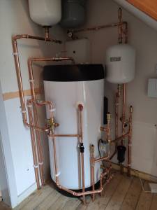
I had a Vaillant Arotherm + 7KW installed last week and an trying to get some snagging issues resolved with the installer. I posted on a Vaillant Facebook group and got loads of feedback and yes the lagging is getting sorted! One thing people couldn't agree on was whether the volumiser on the right was in the correct place, or necessary at all and I wondered it anyone on here had any opinions?
The installer said it may have been left on from a Daikin schematic, because that pump was poor at defrosting, but this one is better and that they would be happy to remove it when they come to do other snagging jobs on Friday. I thought I would seek advice on here before I made a decision. The volumiser is the white tank on the right and I believe the grey tank is a 20/25L buffer.
Very happy to have had my pump installed as we have moved from a coal burning multifuel stove, but I am keen to get it as efficient as possible before the installers move on to the next job!
Heat pump is only doing DHW at the moment - 200L tank set at 45C achieving a rough COP of 3.5. Volumiser gets warm to touch.
Best,
Rob
It is difficult to identify from a photo what task each vessel is performing, but the ones in question look more like expansion vessels rather than volumiser or buffer tank.
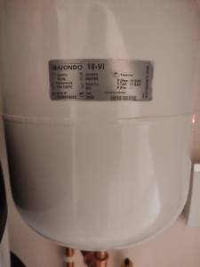
Can you provide a close-up photo of the nameplate on each device?
Hi Derek,
Thanks for taking a look.
This is the one on the right hand side.
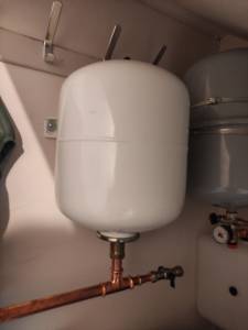
There is no label on the white vessel on the left but it looks to me as if it is probably this:
(Ignore the second photo)
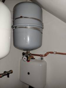
The grey one in the middle doesn't have a label but I think I remember seeing a box with 25L buffer vessel written on it somewhere.
Don't know if that helps at all?
Best,
Rob
The vessel with the nameplate would appear to be the following, which may be being used to add volume to your system. Is it connected within the pipework from your heat pump.
http://www.spatec.co.uk/shop/viewitem.php?productid=680
The white and grey vessels appear to be expansions vessels for the primary and secondary water systems. Their purpose is to allow expansion and contraction of the water within the systems due to change in temperature. They should both have a nameplate which may be round the back or on top.
After having a closer look at your original photo, I think that your system is piped up as follows:-
The pipe coming through the floor furthest on the right would appear to be the flow pipe from your heat pump. This feeds up to the tee where it branches via the horizontal pipe to the electrically operated 3 port valve.
The vertical pipe coming out of the top of the 3 port valve connects to the heating coil within the hot water cylinder. The return pipe from the heating coil connects to a tee near the base of the hot water cylinder.
Pipework from this tee is connected to the bottom connection on the volumiser tank. The top connection on this tank is connected to the return pipe to your heat pump via the filter unit. The outlet from the volumiser tank is also connected to the grey expansion vessel.
The bottom port of the 3 port valve is connected to the flow pipe to the heat emitters and disappears into the floor. The return pipe from the heat emitters connects to the tee feeding back to the heat pump via the volumiser tank.
The mains water supply is via the left most pipe coming through the floor. This feeds into the Pressure Reducing Valve (PRV), after which there is pipework connected to the white expansion vessel and also to the bottom of the hot water cylinder. The pipework feeding out of the hot water cylinder is mounted on the top.
To decide whether to remove the volumiser tank or not, you would need to calculate the volume of water within your heating system, and confirm that this volume is greater than the minimum volume specified in the heat pump manual. Leaving the volumiser in place should not be too detrimental even if it is decided that it is no longer required.
Thanks for the run through Derek. So it seems as though it's in the correct position? I think I'll leave it in place and add a bit of insulation around it.
Had a look a the min system volume for defrost cycle for the Arotherm 7kw and it's 55L. I believe our heating system is over 130L so it does seem as if the volumiser is over kill.
@wobby1 thanks for this - yes his advice was reassuring and system is working very well. I was a bit worried after loads of people had pointed out issues with the install on a Facebook group so I thought I would double check on here. Piping has all been lagged now too.
Posted by: @rob-k@wobby1 thanks for this - yes his advice was reassuring and system is working very well. I was a bit worried after loads of people had pointed out issues with the install on a Facebook group so I thought I would double check on here. Piping has all been lagged now too.
I do believe that the 'knowledge' level on facebook can be a dangerous thing. 😋
The bypass is not installed correctly, as it should incorporate the volumizer, which it doesn't.
-
My house is too big and the Vaillant 7kW heat pump can't heat it when temperatures drop below 4C
11 months ago
-
High air source heat pump running costs – Vaillant AroTherm Plus
11 months ago
-
Vaillant arotherm plus heat pump frost protection
1 year ago
-
Air source heat pump problems - NIBE F 2040 ASHP
1 year ago
-
Vaillant aroTHERM plus not level or flat - what base is best under an external unit?
1 year ago
- 27 Forums
- 2,475 Topics
- 56.9 K Posts
- 314 Online
- 6,165 Members
Join Us!
Worth Watching
Latest Posts
-
RE: If a heat pump can only heat DHW to 50C then what? Issue with 18KW Heliotherm heat pump
Hi, Nothing yet. I've asked customer to measure flow...
By errmm , 4 hours ago
-

RE: High Temp Heat Pumps for fast warm-up of house
I don't know exactly how long it takes to heat up (and ...
By JamesPa , 5 hours ago
-

RE: Need help maximising COP of 3.5kW Valiant Aerotherm heat pump
OK. What Im seeing looks fairly normal TBH: 1 start ...
By JamesPa , 6 hours ago
-
RE: Vaillant Tech Support Flagged Low DT: UFH Return Cold, Suspected Zero Flow
@editor thanks for the tips which I will try before cal...
By DavidB , 7 hours ago
-
RE: Daikin 6kw setup with Dixell controller
@jamespa Many thanks for your reply, a very detailed an...
By CraigH , 8 hours ago
-
RE: Exploring the role of alternative clean heating solutions - Government Consultation
Despite reservations, I found some time to respond to t...
By Rusty , 8 hours ago
-

RE: New Vaillant aroTherm Plus in black - When will it come to the UK?
@crankplus, nope, still not, and I've followed up with ...
By Mars , 8 hours ago
-
RE: Octopus Cosy Heat Pump Owners & Discussion Thread
@agentgeorge Probably, but temperature change at -10 ha...
By AndrewJ , 9 hours ago
-

RE: External wall insulation - your experience
To be clear, my experience was very positive. The journ...
By Batpred , 11 hours ago
-

@foxesfan Re: ‘Servicing’ as @editor has covered in his...
By Toodles , 11 hours ago
-
RE: A Smarter Smart Controller from Homely?
@benson No idea why mine doesn’t work, all I see on ...
By Papahuhu , 12 hours ago
-

RE: Battery sizing - How low can you go!
It seems I am seeing something similar to what you do, ...
By Batpred , 13 hours ago
-
RE: Gaslighting in the heat pump industry – has anyone else experienced this?
Don’t know if this is relevant to this thread, but my A...
By Gruff2001 , 13 hours ago
-
RE: Bosch CS5800i 5kW - Experience So Far
@majordennisbloodnok While getting Home Assistant runni...
By Steelbadger , 1 day ago
-

RE: MCS - BS EN 12831-1:2017 – Heat Loss Survey
Since May 2025 it no longer a requirement in England to...
By JamesPa , 1 day ago
-
RE: Air source heat pump roll call – what heat pump brand and model do you have?
Forum Handel @jancold Manufacturer: Daikin Model: E...
By Jancold , 1 day ago
-
RE: Octopus Cosy 12 Heat Pump Regret: Incredibly Loud, Poor Heating & Constant Hum - Help!
@harriworld it was roughly 3am for an hour as that’s ...
By L2jad , 1 day ago
-

RE: Hoped for improvements not being realised on my Mitsubishi heat pump
I have been wondering that myself. The fact is that, ...
By JamesPa , 1 day ago
-

RE: Filtering Tap Water – Share Your Setup for Cleaner, Better-Tasting Water
I remember when I was in my early 20s I was introduced ...
By Majordennisbloodnok , 1 day ago
-

RE: Setback savings - fact or fiction?
But if it is recorded an an integer, which it seems it ...
By cathodeRay , 2 days ago

