@iantelescope unfortunately your last post does not really answer my question. If you do not know the exact configuration that is understandable.
However it has been brought to my attention that recommendations to improve your hydraulic configuration have been made approximately a year ago by people a lot more knowledgeable than myself so if you have not already, I would suggest to follow their advice and implement those recommendations.
At this moment in time I see you have one of two options
1. Implement the changes recommended to you from a year ago and the control settings I have suggested
2. Remove the entire system and replace with an oil / gas boiler as there are still plenty of competent installers on the market that can do this, so you will be warmer in the winter. You could sell the heat pump on the second hand market to recoupe some of your loses maybe?
Sadly I have run out of advise to solve your issue, sorry
Regards
5 Bedroom House in Cambridgeshire, double glazing, 300mm loft insulation and cavity wall insulation
Design temperature 21C @ OAT -2C = 10.2Kw heat loss, deltaT = 8 degrees
Bivalent system containing:
12Kw Samsung High Temperature Quiet (Gen 6) heat pump
26Kw Grant Blue Flame Oil Boiler
4.1Kw Solar Panel Array
34Kwh GivEnergy Stackable Battery System
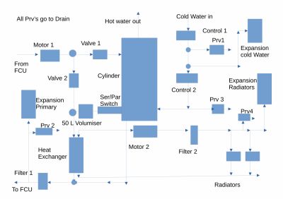
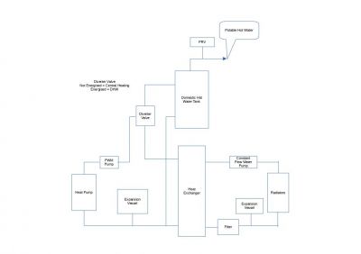
Hi , Please have a look at the Design and layout of my Heat Pump:
Note that my Buffer Tank was installed, at my insistence, with a Valve to allow "Series" or "Parallel" Buffer operation.
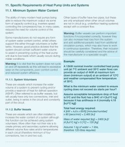
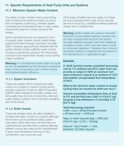
Samsung Warnings about pipe Volume :
Note that my Pipe Volume was , initially, 6 Litres.
MCS Warnings , and sizing of Buffer Tanks:
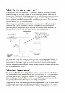
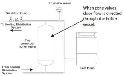
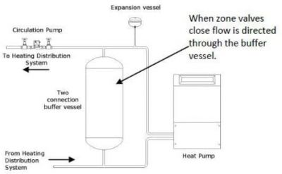
Kendra Positioning and installation of Buffer Tanks:
and again:
Note Also the comments by Kensa that the Buffer tank can be used as a Thermal buffer storing energy during the Cheap periods for use during periods when energy is more expensive, an ideal application of the Octopus "Cosy" tariff.
Note also that the Buffer Tank was NOT installed across the Heat Pump itself.
If installed across the Heat Pump output the Temperature across the Buffer Tank increasing the Temperature to the Shared Hot Water Temperature, circa 50 C, resulting in a yet further increase in the very poor Efficiency after the Heat Pump itself.
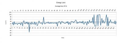
Hot Water is NOT Used because of the increase of losses to 48% !
The Efficiency without HOT Water is currently , an abysmal 29% !
I am well aware that the Buffer tank is "shorting" the input to the Heat Exchanger.
Extensive trials with the Buffer in Series or in Parallel with the Heat Exchanger ports reveal no great difference!
The Buffer tank is ONLY ONE of THREE Different causes for "Short Cycling" :
1: The Honeywell Thermostat
2: The 2091 Water App currently set to Option 2 .
3: The Volume of Water within the Pipe , and Buffer, between the Heat Pump and the Heat Exchanger.
I have spent circa £14000 on replacing the Microbore pipes, Radiators and House Insulation before the start of this fiasco.
I have NO CONFIDENCE in either my former "Installer " , the NIC , the MCS , the RECC , Samsung or Telford , my tank manufacturer. or the "Experts"!
"Experts", only expertise is in defaming , and attacking , other Experts!!
The Only people who actually helped were my local MSP !
The MCS is a private company, with shares on the stock market , masquerading as a Charity!
Hi,
Sadly having Spent some £14000 on the Heat Pump I have no money to either fix the Heat Pump or return it to a Gas boiler.
I only wanted to "Save the planet" but have ended up a Cold, broke and embittered Seventy-Six year old !
Since Ian would appear to be willing to listen to you, the buffer tank should be used as a volumiser in the return pipework to the heat pump, not as shown across the input to the heat exchanger.
After seeing your system and hopefully have understood it correctly, if I was in your position then I would consider the following hydraulic design.
"Hang on a minute, where is the buffer tank?" I hear you cry!
After consideration I do not believe it is needed at all for the following reasons:
1. Placing the buffer tank in parallel with your heat exchange. Water is like electricity it will take the shortest path with the least resistance.
If it is easier to go through your buffer tank then it will effectively starve your heat exchange and radiators of heat. It itself will heat up because it is not dissipating heat and will start sending hot water back to your heat pump, destroying the delta T and upsetting the heat pump. So no good there.
2. Another solution was to convert it into a volumiser by placing it in the return pipe back to the heat pump. Great the heat exchange is no longer starved and the volumiser has achieved its aim, to increase the liquid volume in the primary circuit? Not quite!
If you have 10 litres of water in your pipework and you add a 50 litre tank in the return pipe, yes you increase the static volume from 10 to 60 litres. However heating systems are designed to move heat from one location to another so require the water to actually move which is the more important parameter. So does the volumiser increase the moving volume of water? No.
Physically in a closed loop system only 10 litres of water can move at any one time, ie what is in the pipes. The other 50 litres in the buffer just sits there static, adding no value to the design. If you pump 10 litres per minute into the buffer you will get 10 litres per minute out. You can achieve the same with a standard piece of copper pipe, the only difference is the standard pipe does not have a static 50 litres of fluid in between the input and output.
Based on this I do not see any point in having a buffer unless I have missed something.
Sadly, however, I think this has been another case of fixing an issue that did not exist in the first place. From what I have understood because the heat pump and thermostat have not been configured correctly the system has behaved by mimicking "short cycling". This has caused someone to go on the internet to find a solution to the problem and hey presto the resolution is "put a buffer in the system", when in my humble opinion it just needed the control configuration checking and adjusting first.
The other observation I have made is the DHW and Central heating flow valves. S Plan valves just increase the control wiring and plumbing complexity. In addition, in order to run your heat pump for long periods or continuously, the central heating valve will need to be energised almost 24/7 and I bet your bottom dollar the installers have fitted the more common "normally closed" valve. This increases power consumption, the valve gets very warm / hot and is more prone to frequent electrical failure.
The same result can be achieved with a diverter valve. The path to the central heating circuit is always open when the valve is not energised thus no power is consumed and the heat pump can run as fast and as long as it wants.
When energised the path to the DHW heating coil is then opened and the central heating path is closed. The valve is only energised for as long as it takes to heat the DHW water.
The valve is also controlled by 2 simple wires from the Samsung controller.
I also noticed, but not sure this is an error in your drawing, the filter between your water pump and radiators on the heat exchange secondary side. Filters should be on the return pipework from the radiators to catch any crud and magnetite from the radiators entering your heat exchange and water pump.
Lastly, why is there so many pressure relief valves? The only PRV you should need is on the potable hot water outlet on your DHW tank just in case your immersion thermostat goes faulty causing the water in the DHW tank to boil. The last time I saw that many PRV valves was at Dungeoness power station! 😀
Regards
5 Bedroom House in Cambridgeshire, double glazing, 300mm loft insulation and cavity wall insulation
Design temperature 21C @ OAT -2C = 10.2Kw heat loss, deltaT = 8 degrees
Bivalent system containing:
12Kw Samsung High Temperature Quiet (Gen 6) heat pump
26Kw Grant Blue Flame Oil Boiler
4.1Kw Solar Panel Array
34Kwh GivEnergy Stackable Battery System
@technogeek I have a couple of comments/questions
Posted by: @technogeekBased on this I do not see any point in having a buffer unless I have missed something.
Buffers can
a) increase the engaged system volume, which may reduce cycling time (because you have more water to heat up from the 'turn on' temperature' to the 'turn off' temperature, and provide an additional reserve of heat for defrost. However these functions, if needed, can also performed by a volumiser (two port buffer) fitted in the return, without the efficiency penalty that is more or less inherent in a 4 port buffer (unless controlled correctly, which is frequently not the case)
b) act as hydronic separation, (arguable) needed if for example you have two separate heat sources with separate pumps, however this doesn't apply in the current case
c) act as a system bypass to avoid low flow errors if too many of the emitters have TRV. However (i) they shouldn't and (ii) there are alternative ways to do system bypass which do not suffer the efficiency penalty more or less inherent in a 4 port buffer
So I agree that a 4 port buffer is unnecessary in this (and almost all common) cases, but it is just possible that the system volume is such that a 2 port volumiser is required!
In your diagram shouldn't the diverter valve be after the heat exchanger? If the heat exchanger is needed at all (which I don't think we have established so far) it would be to separate a glycol filled primary from a water filled secondary circuit, to save on volume of glycol needed. One would want to keep the glycol out of the circuit with the DHW tank I would have thought, in case of coil leaks.
Finally my understanding is that, although not actually necessary, it is common practice to have a PRV in the heating circuit, just to prevent the possibility of over-pressuring it when topping up. I know this to my cost, I once topped up my CH system but with the boiler isolated (which is where the PRV and pressure gague are). My mains pressure is 9 bar, and of course because the pressure gauge was isolated it didn't rise, so I kept the fill valve open. Without a PRV this meant that my system pressure rose well above the design value, bursting a radiator. The only good news was that it didn't burst any underfloor pipework, so was relatively easy to fix!
4kW peak of solar PV since 2011; EV and a 1930s house which has been partially renovated to improve its efficiency. 7kW Vaillant heat pump.
@iantelescope I have extracted your Samsung heat pump saga from a general thread to give it a dedicated topic. Please continue updating here.
Get a copy of The Ultimate Guide to Heat Pumps
Subscribe and follow our YouTube channel!
Many thanks for your help .
Buffer Tanks and "Short Cycling"
My Heap Pump has been switching ON and OFF repeatedly for the last two Years.
The ON/OFF Switching was attributed by SAMSUNG-DALLIAM , the Field Operational arm of SAMSUNG to "Short Cycling".
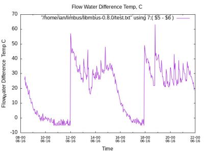
After 18 months I finally , myself, found the principal cause of the ON-OFF SWITCHING to be my Honeywell Thermostat which was set up to SWITCH ON and OFF every 10 minutes.
The principal cause of my ON_OFF SWITCHING WAS MY Honeywell Thermostat , NOT MY BUFFER TANK !.
A 50 l BUFFER was, however, installed by my "installer " on 26th OCT 2022 some four months after the start of the "Installation" to limit the " Short Cycling" .
Buffer tanks , SAMSUNG-DALLIUM and the MCS
The MCS advice on the installation of Buffer tanks makes the assumption that a 5 degree C drop in Water Temperature is Acceptable:
With my Heat Pump during Autumn supplying water output of 41 C this would have reduced the Operating Water Temperature ON the primary side of the Heat Exchanger to 36 C, with a resulting 28 C Water Temperature on the Secondary , Radiator , side of the Heat Exchanger.
My "installer " , initially saying that "THEIR BOYS were perfectly competent to install the Buffer tank " dismissed SAMSUNG-DALLIAM !
My "installer" subsequently "Discovered " the now missing 50 L Buffer TANK "UNDER THE TABLE OF THE , NOW FIRED "TECHNICAL SUPERVISOR".
My "Installer's pair of "Engineers", arriving on 26th OCT 2022 " did NOT know where to install the Buffer tank".
Because of the Temperature Drop across the "IN SERIES " Tank the buffer was installed "IN PARALLEL " following "Kensa"
A valve was installed in series with the Buffer Tank.
The Period between ON-OFF SWITCHING was increased from 8 Minutes to 11 Minutes.
Note that the Buffer-Tank was installed AFTER the Primary side Motor because the buffer tank Temperature would have been increased to 52/55 C, with resulting further increase in net losses when the Heat Pump was supplying the 200 L HOT WATER TANK!
Heat-Exchanger Losses:
The principal cause of the 30 % Energy losses :
Note that Hot-water was not used during the measurement of system loss!
The System Losses were , correctly attributed to the performance of the Heat Exchanger.
The Delta-T Across the primary Heat Exchanger ports was increased by reducing the Flow rates on BOTH SIDES of the HEAT -EXCHANGER.
The in-built Pulse -Width Modulator , PWM Control for the Primary side GRUNDFOSS Motor was found to be faulty with an "Arduino" successfully increasing the Primary , and secondary side Water Delta_t:
"Cosy" Buffer
Using the Octopus "Copy Tariff " with the Buffer tank storing Heat/Energy during periods of Low cost while reducing the Energy used during expensive periods has further improved the efficiency , at least a wee bit!
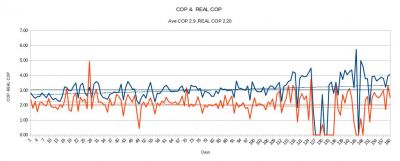
COP and REAL COP
My COP as measured at the output of the Heat Pump itself was poor before reducing the Water Rates on both Heat Exchanger ports:
Both the COP ( Heat-Pump output ) and REAL -COP ( COP at HEAT-EXCHANGER secondary , Radiator ) have recently greatly improved , But so also has the weather!
What do I want!
From the start of this FIASCO I have wanted to remove the 200 L Hot Water tank, Heat Exchanger and BUFFER .
I have repeatedly tried the MCS,NIC,RECC,CA and my MSP ( Member of the Scottish Parliament ).
Only my MSP has helped with the return of ~£5,000 on 15th Dec 2022.
I have spent £1500 on replacing the Microbore pipes as demanded by the "experts".
I have replaced my Radiators at a cost of £2000 as demanded by several "experts".
I have had my Gas pipes under my road/Drive way stripped out , at a cost 0f £922 to avoid "the GAS STANDING Charge!!
I have paid my "installer" some £6000 .
I am paying £42 per month as a repayment for a £2000 Loan from the Scottish Govt.
@editor thank you for moving this thread, I was getting concerned it was way off topic and needed to move 🙂
Posted by: @jamespaSo I agree that a 4 port buffer is unnecessary in this (and almost all common) cases, but it is just possible that the system volume is such that a 2 port volumiser is required!
From the symptoms described by @iantelescope of the heat pump starting up, running for 3 minutes, shutting down for 7 -8 minutes and then running for a further 3 minutes leads me to believe this is an incorrect heat pump setting not short cycling. Samsung have a mode of operation that does just that, run for 3 minutes off for 7 minutes.
The situation was made even worse because the external thermostat (Honeywell Home) which supplies a binary signal was set to cycle 6 times an hour. This setting is normally for gas boilers.
Heat pumps and oil boilers need a cycle rate of 3 times an hour on the Honeywell, which @iantelescope has now set and demonstrated a marked improvement in system behaviour.
He has also indicated that the heat pump installed is undersized ie 5Kw when his property actually needs 6.5Kw.
I am trying to help him because I had practically the same issue, the heatpump running for 3 minutes, completely shutting down for 7 minutes and starting up again while my Honeywell Home thermostat was demanding heat. The house never got warm enough because the heatpump did not run long enough. My issue was not resolved by implementing buffer tanks and the usual solutions for "short cycling" as this would have actually made the issue worse.
My issue was resolved by having the thermostat on 3 cycles per hour, the heat pump set to an option that forced the heatpump to run continuously while the thermostat demanded heat. I then balanced the power output of the heat pump with the heat load (house) for different outside temperatures using the weather compensation. Now the thermostat duty cycle is practically 100% most of the time, the heatpump runs long enough to actually create heat and maintains the flow temperature close to the weather compensation value by switching the compressor in and out or changing its speed accordingly. The house now achieves 21C and stays there 🙂
My system now behaves as close to a system with a built in thermostat talking constantly to the heat pump which as I have gathered from this forum, is the ideal set up.
With @iantelescope system, providing his heat exchanger is capable of transferring the required heat to the secondary circuit and the heat source is matched to the heat load via weather compensation, I cannot see any reason why his system should short cycle. Increasing the water volume in my humble opinion just increases the heating time to resolve a "cycling" problem while sacrificing the heating of the house which I thought was the primary reason for a heating system 🙂
5 Bedroom House in Cambridgeshire, double glazing, 300mm loft insulation and cavity wall insulation
Design temperature 21C @ OAT -2C = 10.2Kw heat loss, deltaT = 8 degrees
Bivalent system containing:
12Kw Samsung High Temperature Quiet (Gen 6) heat pump
26Kw Grant Blue Flame Oil Boiler
4.1Kw Solar Panel Array
34Kwh GivEnergy Stackable Battery System
If my memory serves me correctly, I do believe that it was pointed out quite so time ago that trying to control IAT using an on/off type thermostat was far from ideal, and may only be beneficial during milder weather conditions. I don't believe that the type of thermostat was explored in detail, so was assumed to be an on/off type, without any form of cycling.
It was pointed out that the Plate Heat Exchanger (PHE) was probably having quite a detrimental affect on system operation and overall efficiency and should be removed, along with the suggestion that the installed buffer tank be re-piped to create a volumiser. As far as I am aware none of these suggestions were heeded.
The primary reason to have an on/off type thermostat within a heat pump system should be to limit the IAT when the heat pump is below minimum constant output, or when solar gain is raising IAT above a desired maximum. A cycling type thermostat should be avoided if at all possible.
As James has pointed out, a volumiser could be beneficial during defrost cycles to provide additional thermal energy. Without additional volume within the primary circuit then efficient defrosting is greatly dependent upon both the primary and secondary water pumps being operational and good reverse thermal energy transfer through the PHE.
During milder weather conditions it is quite probable that a heat pump will cycle even when any thermostat is constantly requesting heating. This is because limits are set within the heat pump controller to prevent the Leaving Water temperature (LWT) from going too high or too low. The frequency of cycle then becomes dependent upon the physical location of the controlling thermistors and how quickly they heat up and cool down along with the setting of the limits.
@derek-m I appreciate what you are saying and in an ideal world it would be best to remove everything and start again however I get the impression that is not an option and all we can do is try and improve on what we have.
I have not suggested the removal of the heat exchanger because due to the lack of information I (and possibly others) have had to assume there is glycol in the primary circuit requiring such a component.
The model of thermostat (same as mine) Ian has has cycling options of 3, 6, 9 and 12 cycles per hour. Set to 3 each cycle time is 20mins long and the "on" portion of that 20mins is varied depending on how closely matched the heat source is to the heat load. By getting an equal balance it is possible to get the thermostat to demand heat near 100%, ie < 17mins out of 20mins per cycle if that makes sense. In very mild weather the thermostat is intelligent enough to actually reduce the number of cycles down to 2 or even 1 cycle an hour.
I get the impression this cycling configuration has only been discovered recently by @iantelescope
Posted by: @derek-mThe primary reason to have an on/off type thermostat within a heat pump system should be to limit the IAT when the heat pump is below minimum constant output, or when solar gain is raising IAT above a desired maximum. A cycling type thermostat should be avoided if at all possible.
It is possible to do this by setting the thermostat 2 -3 degrees above what you want and it will call for heat 100% of the time but it also requires the Samsung controller to be in the correct mode of operation. The mode I believe it was (is) in is mode 4 which causes the heat pump to switch on for 3 mins / off 7 mins continuously while the thermostat is demanding heat thus looking like the pump is short cycling. Furthermore the weather curve needs setting correctly so the desired room temperature is reached and maintained but the target temperature of the thermostat is never reached.
Due to my system being bivalent, my heat pump at present does not run at outside temperatures below zero so defrost is not currently a process that happens. However it does do frost protection operations and opens the valve to the DHW storage tank to use this as a source of heat not the radiators so I am assuming this would also be the case for Ian's system.
The one time that the heat pump did do a defrost (while I was initially setting up my system) I reckon it uses an electric heater because the electricity meter went up to 7Kwh and the back garden looked like a Turkish sauna! 😀 I was not aware of it taking heat from the radiators while in this mode so I would be surprised the heat changer would be an issue.
As there are some assumptions in my analysis I could stand corrected on some points 🙂
5 Bedroom House in Cambridgeshire, double glazing, 300mm loft insulation and cavity wall insulation
Design temperature 21C @ OAT -2C = 10.2Kw heat loss, deltaT = 8 degrees
Bivalent system containing:
12Kw Samsung High Temperature Quiet (Gen 6) heat pump
26Kw Grant Blue Flame Oil Boiler
4.1Kw Solar Panel Array
34Kwh GivEnergy Stackable Battery System
- 27 Forums
- 2,495 Topics
- 57.8 K Posts
- 947 Online
- 6,220 Members
Join Us!
Worth Watching
Latest Posts
-

RE: Electricity price predictions
I agree incentives are needed. We are an unusual home b...
By Batpred , 5 hours ago
-
RE: Testing new controls/monitoring for Midea Clone ASHP
@tasos interesting. I might look into that. My other op...
By benson , 7 hours ago
-
RE: Our Experience installing a heat pump into a Grade 2 Listed stone house
@robs Do you need IAT for this to work? Don’t curren...
By Travellingwave , 9 hours ago
-
RE: Struggling to get CoP above 3 with 6 kw Ecodan ASHP
@goodbyegas Hi Fellow Ecodan owner here. Looking a...
By Travellingwave , 9 hours ago
-

RE: Say hello and introduce yourself
You can send private messages via the Messages (envelop...
By cathodeRay , 13 hours ago
-
RE: Peak Energy Products V therm 16kW unit heat pump not reaching flow temperature
With complete radio silence from Peak and no sign of th...
By DaveC , 13 hours ago
-
RE: Humidity, or lack thereof... is my heat pump making rooms drier?
Yes, ours dropped by about 25% RH. I figured it was a c...
By Papahuhu , 14 hours ago
-
RE: The Hidden Secret to a Successful Heat Pump: Pipe Size Matters
I'm wondering if I need to do any pipe upgrades. My hea...
By Falesh , 15 hours ago
-
RE: Solis inverters S6-EH1P: pros and cons and battery options
@batpred The Pace BMS also isn't the best with it's ...
By Bash , 15 hours ago
-

I understand now what you were referring to. This look...
By trebor12345 , 15 hours ago
-
RE: What determines the SOC of a battery?
@batpred I would consider changing your balance star...
By Bash , 16 hours ago
-

RE: Setback savings - fact or fiction?
This illustrates what I am getting at, even apparent st...
By cathodeRay , 20 hours ago
-

No you arent, because you dont need any, and furthermor...
By JamesPa , 21 hours ago
-

RE: Oversized 10.5kW Grant Aerona Heat Pump on Microbore Pipes and Undersized Rads
As I mentioned earlier most radiators have a power outp...
By JamesPa , 21 hours ago
-

@painter26 — they (the analogue gauges) are subtly diff...
By cathodeRay , 1 day ago
-

RE: Getting ready for export with a BESS
I would have not got it if it was that tight
By Batpred , 2 days ago
-
RE: Need help maximising COP of 3.5kW Valiant Aerotherm heat pump
@judith thanks Judith. Confirmation appreciated. The ...
By DavidB , 3 days ago
-

RE: Recommended home battery inverters + regulatory matters - help requested
That makes sense. I thought better to comment in this t...
By Batpred , 3 days ago
-
Bosch CS5800i 7kW replacing Greenstar Junior 28i
My heat pump journey began a couple of years ago when I...
By Slartibartfast , 3 days ago
-

RE: How to control DHW with Honeywell EvoHome on Trianco ActiveAir 5 kW ASHP
The last photo is defrost for sure (or cooling, but pre...
By JamesPa , 3 days ago
-

RE: Plug and play solar. Thoughts?
Essentially, this just needed legislation. In Germany t...
By Batpred , 3 days ago
-
RE: A Smarter Smart Controller from Homely?
@toodles Intentional opening of any warranty “can of wo...
By Papahuhu , 3 days ago
-
RE: Safety update; RCBOs supplying inverters or storage batteries
Thanks @transparent Thankyou for your advic...
By Bash , 3 days ago

