Before I spend too much time and effort reading back through your previous posts could you please confirm that you wish to try to resolve the issues with your system.
If so, it would be useful if you could provide a schematic diagram of your system detailing the various component parts and the interconnecting pipework.
I would also suggest that you obtain some suitable thermometers with which to measure various temperatures around the system.
I think he is very pleased!
Toodles, heats his home with cold draughts and cooks food with magnets.
Many thanks Derek.
Why ?
I am a 76 year old with a Heat Pump whose winter running costs are about 60% greater than the Gas boiler it replaced.
My "installer " has now been STRUCK-OFF by the NIC for the third time.
The NIC have now abandoned me saying that " nothing can be done".
The Circuit Diagram
The "Circuit Design" is shown in the attached pdf:
Measurements.
I have the measured, and recorded, for the last eight months:
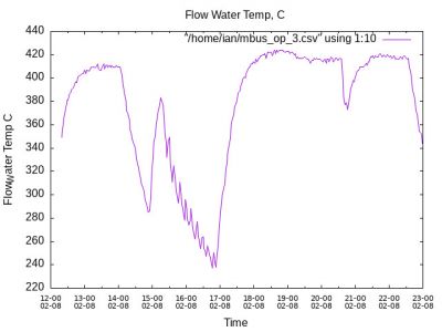
1: The Heat Pump water output temperature using a K type Thermocouple attached to a data logger.
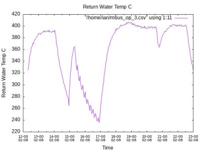
2: The Heat Pump water return temperature using a K type Thermocouple attached to a data logger.
3: The Radiator circuit output water return temperature using a K type Thermocouple attached to a data logger.
4 :The Radiator circuit return water temperature using a K type Thermocouple attached to a data logger.
5: The Heat Exchanger input Temperature using a DS18B20 sensor attached to an Arduino.
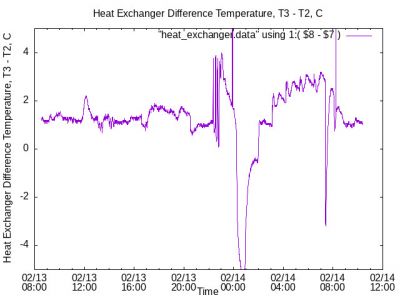
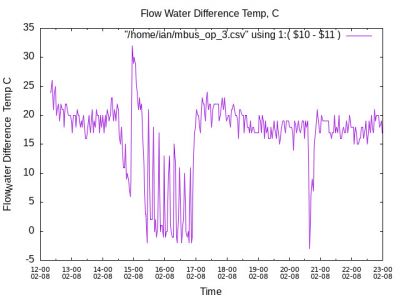
6: The Heat Exchanger Difference Temperature, Input - Output using a DS18B20 sensor attached to an Arduino.
7: The Total power and Energy used by the Heat Pump using an Arduino.
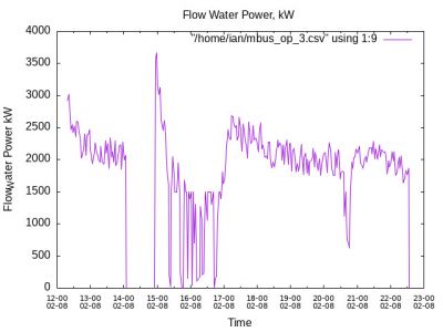
8: The Power , Flow rate , Output and return Temperatures using a "Sharky" Water power meter attached to start of the radiator water circuit.
I have increased the Delta T across the Heat Exchanger by reducing the water flow rates on both the input and radiator ports of the Heat Exchanger using yet another Arduino.
The reduced Water flow rates were adjusted using the PWM motor controls fed, and recorded by another Arduino.
Conclusions
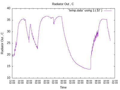
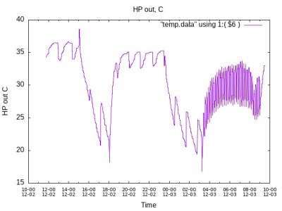
1: The Temperature of the pipe water outlet from the Heat Pump is shown in :
Notice that the Buffer is dumping it's water during the night between 1 am and 6 am.
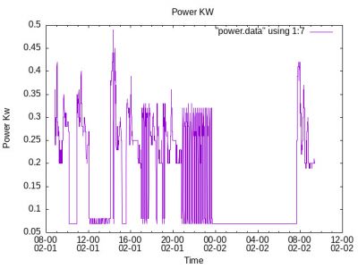
The Power consumed on the same night is :
Notice that the No power is consumed between 1 and 6 am.
The Conclusion is that the Buffer is working , as designed , and asked for by Samsung -Dalliam.
Also note the extensive short Cycling ................................................
The Conclusion is surely that the buffer tank should be installed directly across the Heat Pump water outlets.
Moving the Buffer tank, will however , add further inefficiency to a system that is already very inefficient, and costly!
See the MCS document attached
A similar conclusion is reached by Kendra
Many thanks for your understanding and patience.
My own idea for simultaneously improving my Heat Pump Efficiency and stopping the continuous "Short Cycling" from destroying the system would be:
1) Replace the Hot water Tank with an Electrically heated on-demand immerser.
Perhaps using the immerser , and tank, already fitted, bypassing the Heat pump immerser controls!.
2) Given the primary water pipes only contain 6 litres of water , install the 50 Litre Volumiser across the output pipes of the Heat pump.
The resulting 56 litres of water will increase the Cycling Damping by 56/6 , or 9 fold!.
Without the Hot water tank , and given that the Volumiser/Buffer is located in my kitchen , use the resulting Volumiser leaking heat to heat my kitchen.
3) Keep the Heat exchanger to isolate the Radiator circuit from the Heat Pump outputs.
4) Disable, or switch OFF the Hot water supply valves.
This I could easily do myself.........
ian
Thank you for providing the data, I remember seeing the schematic diagram some time ago. To clarify, I assume that Motor 1 and Motor 2 are driving the primary and secondary water pumps respectively.
While I agree to a certain extent with Kendra's philosophy regarding buffer tanks, I still maintain that a volumiser should be used in preference to a buffer tank. Kendra also mention zone valves closing which is something which should be avoided in a heat pump system.
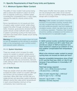
It is my considered opinion that the primary purpose of a volumiser is to help provide thermal energy for defrost cycles, especially if the volume of water within the heat emitters and pipework is limited. It would be useful if you could check the size and type of all the radiators and then check the volume of water which each contains. The Screwfix website is a good source of useful data unless you know the actual manufacturer.
The first thing that I noticed is that your diagram shows the primary water pump before the volumiser, which is not as shown in the Kendra document.
Just to confirm that you have a 12kW Samsung heat pump.
Please provide details of any thermostats or TRV's and how your system is being operated.
I will have a read through the manual and come back with further tests and possible suggestions.
Posted by: @iantelescopeMany thanks for your understanding and patience.
My own idea for simultaneously improving my Heat Pump Efficiency and stopping the continuous "Short Cycling" from destroying the system would be:
1) Replace the Hot water Tank with an Electrically heated on-demand immerser.
Perhaps using the immerser , and tank, already fitted, bypassing the Heat pump immerser controls!.
2) Given the primary water pipes only contain 6 litres of water , install the 50 Litre Volumiser across the output pipes of the Heat pump.
The resulting 56 litres of water will increase the Cycling Damping by 56/6 , or 9 fold!.
Without the Hot water tank , and given that the Volumiser/Buffer is located in my kitchen , use the resulting Volumiser leaking heat to heat my kitchen.
3) Keep the Heat exchanger to isolate the Radiator circuit from the Heat Pump outputs.
4) Disable, or switch OFF the Hot water supply valves.
This I could easily do myself.........
ian
I am sure @derek-m will also comment and I would advise to see what he says as well but...
I wouldn't do what you are suggesting, its unlikely to make an improvement. The current circuit diagram looks like an unmitigated disaster.:
- The volumiser completely short circuits flow-> return creating unnecessary circulation through the primary
- The heat exchanger is plumbed wrongly (if the diagram is an accurate representation) - primary and secondary should flow in opposite directions through the heat exchanger
can you answer these questions:
- What controls do you have other than the Samsung controller?
- What are your weather compensation (water law) settings?
- Is there glycol in the primary?
My instinct would be to replumb the volumiser into the return only and ditch the heat exchanger and second pump (subject to the 'glycol' answer). Id then turn any TRVs or thermostats up to full and adjust WC to get the right temperature, balancing the rads if necessary.
But first I would measure the temperatures at the four ports of the heat exchanger to see whether its part of the problem, or merely an unnecessary component but not doing any actual harm
4kW peak of solar PV since 2011; EV and a 1930s house which has been partially renovated to improve its efficiency. 7kW Vaillant heat pump.
@derek-m .
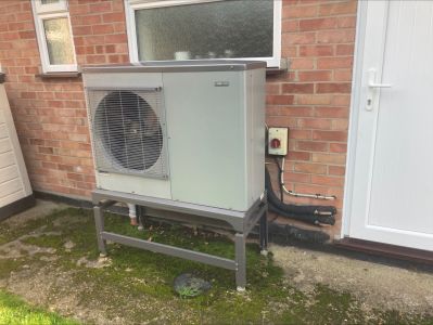
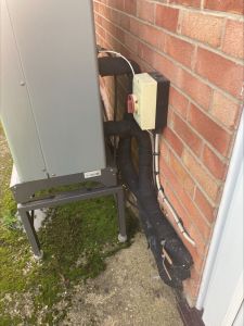
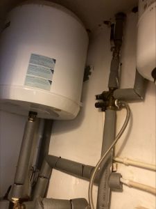
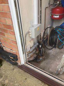
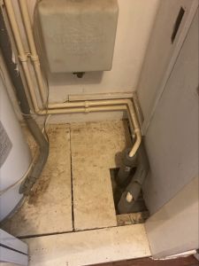
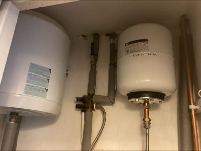
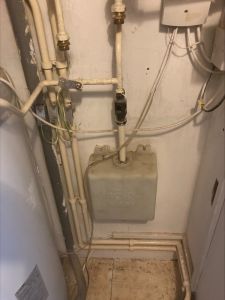
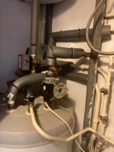
Many thanks for offering to assist here Derek. Not something I was expecting but would be great if an expert could see if anything is amiss. I have taken a number of photos and will upload here. 15 for now as this is limit. I have a few more I will look to add later
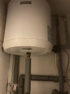
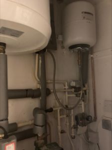
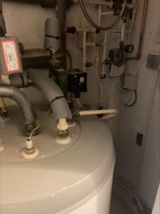
The first thing that I noticed is sections of un-insulated pipework and the quality of insulation on the sections that have been done is not that good.
It would be useful if you could provide a schematic diagram detailing the component parts of your system and the interconnecting pipework.
Also details of how the system is being operated and the various parameter settings.
Hi Everyone,
I have eventually received a reply to the e-mail that I sent to my MP in late January, a copy of which is attached. As I anticipated it would appear to have been a complete waste of time.
@derek-m It never ceases to annoy me that we pay inordinately large proportions of our hard earned income so that twerps in official office can churn out cr*p like this and at the same time appear to be providing the public with good levels of service. HARRUMPH Toodles.
Toodles, heats his home with cold draughts and cooks food with magnets.
Many thanks for your patience Derek.
I will not , again, go through the 18 month history of my Heat Pump odyssey, It serves no purpose, with m y "installers" and the NIC abandoning the Heat Pump.
Answers to your questions.
Size of Heat Pump required.
1) A 6.5 Kw Heat Pump was initially selected by my "installer" for my house on the basis of a MCS survey.
2) My "installer", with a Samsung 5kW heat Pump readily available , produced a second MCS survey, justifying fitting the 5Kw on the basis of a second MCS Survey.
3) This second MCS survey was produced by altering the Wall thermal conductivity until the total power required was less than 5Kw.
4) The behaviour of my Installer resulted in his final demise.
Volumiser or Buffer tank.
1) Samsung -Dallium asked for a 50 litre Buffer tank to cure the de-icing problem without specifying Where the Buffer tank was to be installed.
2) My "installer" installed a 50 litre Buffer tank, two months later, fitted across the Heat Exchanger ports.
3) The Buffer tank was fitted after the primary motor to avoid increasing the buffer tank water temperature to that of the Hot water heat Pump supply , 55..60 C.
4) The Buffer tank , with only two ports used, was , at my insistence, fitted with a valve to allow buffer deselection.
Heat Exchanger.
1) The Heat pump arrived with a Heat Exchanger attached to the hot water tank. The Heat exchanger is correctly orientated, input to output.
What now?
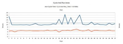
1) The Heat Pump is still "Short Cycling" with a cycle time of 11 minutes up to 90 times per day.
2) This "Short Cycling" occurs at high , ~4kW And low Powers , ~ 1.3 kW NOT just during autumn and Spring!
3) The System supplies <2 kW during cold winters nights resulting in my use of a 1.6 kW backup heater.
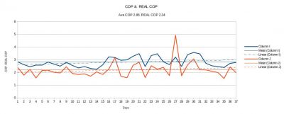
4) The COP and my own REAL-Cop , the COP calculated AFTER the Tank , at the start of the radiator circuit:
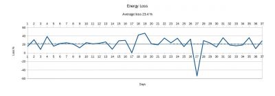
5) the losses , computed by the ratio of the power from the Sharky water meter positioned AFTER the tank, to the power displayed on the Samsung Front panel .
The Average COP is currently 2.86 while the REAL-COP is 2.24.
The Heat pump is still consuming 60-80% more than the Gas boiler it replaced.
- 27 Forums
- 2,495 Topics
- 57.8 K Posts
- 1,312 Online
- 6,220 Members
Join Us!
Worth Watching
Latest Posts
-

RE: Our Experience installing a heat pump into a Grade 2 Listed stone house
@travellingwave Looking forward to hearing the rest ...
By MK4 , 20 minutes ago
-
RE: Solis inverters S6-EH1P: pros and cons and battery options
As a side note I observed the the charge/discharge time...
By Bash , 22 minutes ago
-
RE: Testing new controls/monitoring for Midea Clone ASHP
@benson Thanks for new graph. Initial reaction is that ...
By Tasos , 37 minutes ago
-

RE: Humidity, or lack thereof... is my heat pump making rooms drier?
That’s my pleasure, @andrewj. The only challenge now is...
By Majordennisbloodnok , 9 hours ago
-
RE: Electricity price predictions
@toodles @skd Then there is not going to be much from t...
By ChandyKris , 10 hours ago
-
RE: What determines the SOC of a battery?
@batpred Ironically you didn't have anything good to...
By Bash , 11 hours ago
-
RE: Setback savings - fact or fiction?
True there is a variation but importantly it's understa...
By RobS , 11 hours ago
-

Below is a better quality image. Does that contain all ...
By trebor12345 , 12 hours ago
-
Sorry to bounce your thread. To put to bed some concern...
By L8Again , 12 hours ago
-

@painter26 — they (the analogue gauges) are subtly diff...
By cathodeRay , 12 hours ago
-
RE: Struggling to get CoP above 3 with 6 kw Ecodan ASHP
Welcome to the forums.I assume that you're getting the ...
By Sheriff Fatman , 19 hours ago
-
RE: Say hello and introduce yourself
@editor @kev1964-irl This discussion might be best had ...
By GC61 , 21 hours ago
-

RE: Oversized 10.5kW Grant Aerona Heat Pump on Microbore Pipes and Undersized Rads
@uknick TBH if I were taking the floor up ...
By JamesPa , 1 day ago
-

RE: Getting ready for export with a BESS
I would have not got it if it was that tight
By Batpred , 2 days ago
-
RE: Need help maximising COP of 3.5kW Valiant Aerotherm heat pump
@judith thanks Judith. Confirmation appreciated. The ...
By DavidB , 2 days ago
-

RE: Recommended home battery inverters + regulatory matters - help requested
That makes sense. I thought better to comment in this t...
By Batpred , 2 days ago
-
Bosch CS5800i 7kW replacing Greenstar Junior 28i
My heat pump journey began a couple of years ago when I...
By Slartibartfast , 2 days ago
-

RE: How to control DHW with Honeywell EvoHome on Trianco ActiveAir 5 kW ASHP
The last photo is defrost for sure (or cooling, but pre...
By JamesPa , 2 days ago
-

RE: Plug and play solar. Thoughts?
Essentially, this just needed legislation. In Germany t...
By Batpred , 2 days ago
-
RE: A Smarter Smart Controller from Homely?
@toodles Intentional opening of any warranty “can of wo...
By Papahuhu , 2 days ago
-
RE: Safety update; RCBOs supplying inverters or storage batteries
Thanks @transparent Thankyou for your advic...
By Bash , 2 days ago
-
RE: Air source heat pump roll call – what heat pump brand and model do you have?
Forum Handle: Odd_LionManufacturer: SamsungModel: Samsu...
By Odd_Lion , 2 days ago
-
RE: Configuring third party dongle for Ecodan local control
Well, it was mentioned before in the early pos...
By F1p , 2 days ago


