Posted by: @derek-mHi Mars,
You have had discussions with the staff at MCS. Whilst they set the standards installation, do they have any responsibility for enforcement or is that down to some other organisation? If so who?
How do they deal with complaints about poor installation and commissioning by accredited installers?
Maybe time for a further video.
https://mcscertified.com/complaints-compliance/
Help from MCS is reliant upon the customer knowing that there is a problem. In cases where the heating system works in a fashion, but is inefficient because it was not configured correctly, who is actually checking other than the customers themselves.
It would appear that there needs to be better policing of system installation and performance, to weed out the installers who provide a substandard service.
@derek-m: Conditions for noise occurring:
The target temperature was 34 degrees with 8 degrees outside.
I monitored the leaving water temp and the water temp PHE and the flow.
For example at 16:13pm is said the temps were 38/39 and flow was 10.7
At 16:21 it said temps were 32/33 and flow 26.4.
16:32 to flow drops to 0 and stops.
then it goes up to 30.01 and is saying that the leaving water temp and PHE is 31/32 respectively.
Or another example:
13:27 it was 33/34 with a flow at 26.4
13:28 it was 32/33
13:29 it was 32/32
13/31 it was 31/32 and flow went to 0, paused and then went up to 31.4
and another:
15:07 38/39 flow 10.7/11.4
15:21 39/39 flow 10.7.11.4
15:23 34/35 flow increased to 26.4
I've been watching it as best I can between meetings since 11:50. It will run noisily at 30l for 20 to 30 mins or so. As the temp increases the flow decreases and then the temp seems to drop actually quite suddenly and then it fires up again with the flow to increase the temperature above the target.
At 16:34 we are at 30.6l with temps at 33/34.
(It may not be relevant but the pump was faulty when installed and they replaced one PCB with a new part from Daikin and then another PCB taken from a display machine due to supply issues).
The noise increases as the flow increases.
Thanks for your help
@derek-m The noise is in the big pipes (and the tank on the wall in the earlier photos). These seem to be pretty big and these are all new. It does go into a smaller pipe when it meets the old heating system (including the towel rail which seems to link into the circuit before the rest of the heating. The noise in the radiators in very minimal. The noise in those large pipes, that tank and the towel rail is load at high flow volumes.
Posted by: @bridgetjohn@derek-m The noise is in the big pipes (and the tank on the wall in the earlier photos). These seem to be pretty big and these are all new. It does go into a smaller pipe when it meets the old heating system (including the towel rail which seems to link into the circuit before the rest of the heating. The noise in the radiators in very minimal. The noise in those large pipes, that tank and the towel rail is load at high flow volumes.
Hi Bridget,
It is difficult trying to assess precisely what is happening within your system, when one is not actually present to witness it oneself.
I believe that the tank on the wall is the backup heater, which may contain an automatic air bleed valve, which should be left open for correct operation. Personally I don't think that your system required a backup heater to be installed in the first place, and I would suggest that you ask your installer to justify the decision to install one.
The main pipework of the system should be the same diameter, and should only reduce in diameter where it branches off to other areas.
If the weather compensation is correctly adjusted, I would expect your heat pump to run for extended periods at the calculated LWT, and periodically carry out the defrost cycle. Once up and running I would expect the flow rate to be fairly constant whilst the heat pump is operational, and should not be varying to a great degree.
The fact that you have had two PCB's replaced, one with a used unit, with make me a little concerned. Did the technician explain why the PCB's failed.
My suggestion would be that you write to your installer, highlighting the problems that you are experiencing, ask them to complete the installation by fitting the missing insulation on the pipework and completing filling in the documentation with a list of all the parameter settings.
Also ask them to fully prove that your system is operating in a consistent, efficient and reliable manner.
If the installer fails to respond, or fails to provide you with a system that is fit for purpose, then you would have grounds to complain to MCS.
@derek-m Thank you again for your help.
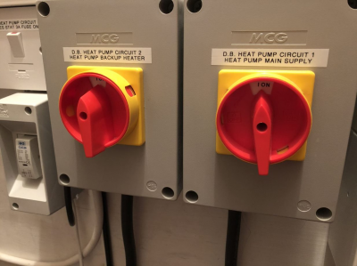
I think you are right that this is a backup heater. There are definitely controls for a backup heater - see picture below:
There is a valve underneath that tank but it is now fully closed, I think, at 0.5 because it was "snoring" when it was set to 0.3 i.e. not a consistent flow. Is that the air bleed valve?
or is it this?
The unit supplied was faulty and that's why they replaced the PCB boards. The first one was sent by Daikin and installed by them. The second one didn't arrive in good time from Belgium and thus the installer took one out of a display unit to try and speed up the repair.
I think the pipework looks consistent.
We have been emailing the installer and will continue to do so. The perspective though that there is something wrong and this noise is not normal is helpful as this is all new technology and its hard to know what normal is supposed to look like.
The only other thing in the airing cupboard is this:
Not sure what that's for either.
Thanks again
Hi Bridget,
I have attached a copy of the Daikin backup heater manual so that you will recognise it should you trip over it.
The item that I thought may the backup heater, the upper of the two white cylinders, may be a volume cylinder. Does it have a nameplate?
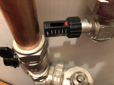
The second photo is the pressure relief bypass valve.
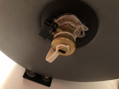
The third photo looks like it could be a drain valve, but it is not clear where it is installed.
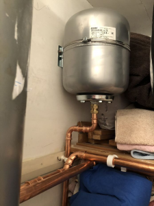
The fourth photo shows the galvanised (silver coloured) expansion vessel, which accommodates the expansion and contraction of the water as it heats up and cools down.
According to the 280 page manual, there is the facility to limit the water pump speed, but this is something that you would need to discuss with your installer.
@derek-m Thank you. The tank on the left has no markings that I can see. It is insulated in a grey jacket bit has one pipe in and one out but no connection to any electrical installation. The third picture above of the valve is at the bottom of this cylinder.
I can’t see anything that looks like the back up heater in the manual you attached.
it looks to me like the electric cables for both heat pump and back up run under the large hot water storage tank.
Optional:
Back-up heater EKLBUHCB6W (can be rewired to 3V/6V/9W )
i think the backup might be within the outdoor unit as this is an option in a manual I found when I googled it. That would make sense as the cables seem to go outside I think. That would conclude that the cylinder on the left is therefore not a backup heater.
Posted by: @bridgetjohnOptional:
Back-up heater EKLBUHCB6W (can be rewired to 3V/6V/9W )i think the backup might be within the outdoor unit as this is an option in a manual I found when I googled it. That would make sense as the cables seem to go outside I think. That would conclude that the cylinder on the left is therefore not a backup heater.
Hi Bridget,
I think that you are correct about the backup heater being located within the ASHP unit.
@hydros Is the grey cylinder in the photos at the beginning of this thread a buffer tank?
@heat-pump-newbie it’s a large volumiser tank, I used to have one fitted on my system. It’s used in place of a backup heater, to ensure minimum volume of water is retained in the primary circuit, if all radiators are shut down by TRVs. My 11kw system needed a volume of 80ltr without a backup heater, 20ltr with a backup heater. My understanding is that it’s utilised during defrost cycles to reduce cold water circulating back round the heating circuit (at least that was the way it was explained to me).
I’ve not looked through all 7 pages of this thread thoroughly, sorry have been away for a while so not keeping up to date on this forum, but the black valve that was causing noise looks like an auto-bypass valve on first inspection. If this is triggering regularly it implies it’s not set correctly and/or you have TRVs interfering with the flow (that’s assuming you have radiators and not underfloor heating, I’ve not checked for that detail). If my assumption is correct we can solve this unless you’ve already sorted it.
- 27 Forums
- 2,495 Topics
- 57.8 K Posts
- 262 Online
- 6,220 Members
Join Us!
Worth Watching
Latest Posts
-
RE: Setback savings - fact or fiction?
@cathoderay The input power is largely determined by...
By RobS , 11 minutes ago
-

RE: Humidity, or lack thereof... is my heat pump making rooms drier?
@editor, this is now an example of greenwashing in the ...
By Majordennisbloodnok , 22 minutes ago
-

RE: Electricity price predictions
@transparent Im impressed by all your work on this. ...
By JamesPa , 2 hours ago
-

RE: Solis inverters S6-EH1P: pros and cons and battery options
Just to wrap this up here for future readers: The S...
By Batpred , 2 hours ago
-
RE: Struggling to get CoP above 3 with 6 kw Ecodan ASHP
Welcome to the forums.I assume that you're getting the ...
By Sheriff Fatman , 2 hours ago
-

RE: What determines the SOC of a battery?
I agree. Fogstar confirmed that the Seplos BMS does ...
By Batpred , 3 hours ago
-
RE: Say hello and introduce yourself
@editor @kev1964-irl This discussion might be best had ...
By GC61 , 4 hours ago
-

RE: Testing new controls/monitoring for Midea Clone ASHP
@benson — as @tasos suggests, plotting multiple variabl...
By cathodeRay , 6 hours ago
-

@painter26 — as @jamespa says, it's for filling and re-...
By cathodeRay , 8 hours ago
-

RE: Oversized 10.5kW Grant Aerona Heat Pump on Microbore Pipes and Undersized Rads
@uknick TBH if I were taking the floor up ...
By JamesPa , 18 hours ago
-

RE: Getting ready for export with a BESS
I would have not got it if it was that tight
By Batpred , 20 hours ago
-
RE: Need help maximising COP of 3.5kW Valiant Aerotherm heat pump
@judith thanks Judith. Confirmation appreciated. The ...
By DavidB , 23 hours ago
-

RE: Recommended home battery inverters + regulatory matters - help requested
That makes sense. I thought better to comment in this t...
By Batpred , 24 hours ago
-
Bosch CS5800i 7kW replacing Greenstar Junior 28i
My heat pump journey began a couple of years ago when I...
By Slartibartfast , 24 hours ago
-

RE: How to control DHW with Honeywell EvoHome on Trianco ActiveAir 5 kW ASHP
The last photo is defrost for sure (or cooling, but pre...
By JamesPa , 1 day ago
-

RE: Plug and play solar. Thoughts?
Essentially, this just needed legislation. In Germany t...
By Batpred , 1 day ago
-
RE: A Smarter Smart Controller from Homely?
@toodles Intentional opening of any warranty “can of wo...
By Papahuhu , 1 day ago
-
RE: Safety update; RCBOs supplying inverters or storage batteries
Thanks @transparent Thankyou for your advic...
By Bash , 1 day ago
-
RE: Air source heat pump roll call – what heat pump brand and model do you have?
Forum Handle: Odd_LionManufacturer: SamsungModel: Samsu...
By Odd_Lion , 1 day ago
-
RE: Configuring third party dongle for Ecodan local control
Well, it was mentioned before in the early pos...
By F1p , 2 days ago
-

RE: DIY solar upgrade - Considering adding more panels
I know this is a bit old, but it made me wonder what co...
By Batpred , 2 days ago
-

RE: New Vaillant aroTherm Plus in black - When will it come to the UK?
@majordennisbloodnok Daikin, take note! (In fact, I hav...
By Toodles , 2 days ago
-

RE: Midea ASHP – how to set weather compensation
@mk4 — good work! First, I agree, no evidence of cycl...
By cathodeRay , 2 days ago

