Seplos Mason DIY Kit - Ancillaries - Advice
Hi all and thanks in advance for any assistance,
I wondered if someone with experience of the Seplos Mason 280L or 280 could offer advice on what ancillaries I should purchase for my planned install.
Although Fogstar (the retailer I am using for the Mason) have been helpful with general questions, it has been difficult to get an exact list of what I need to buy (and from where) alongside their systems.
The inverter I plan to use - Sunsynk 8K-SG01LP1-EU 8.8kW Ecco Hybrid 1Ph Inverter (tradesparky.com)
I believe for my planned system of 3x SEPLOS 15.2kwh packs all I need is the following:
150 amp - fused isolation switch between batteries and inverter
4* Positive Copper Cables 95mm2 (M8 lugs or seplos connectors? How long should they all be?)
4* Negative Copper Cables 95mm2 (M8 lugs or seplos connectors? How long should they all be?)
Earth between all sets
A diagram of how to wire these would be useful as I can't find one as yet!?
Can anyone link me to the cables with the correct "ends" assuming i go for the 280L on wheels?
If somebody has a diagram or picture with explanation of their system then that would be very useful to ensure I get the correct bits. I plan to order later this week subject to having all of the required information.
I do have a professional electrician stood by to do the final install of the system to include commissioning however I plan to have everything built and set up ready for just a check over and final connection to the board.
I have had experience wiring up 2 x Seplos Mason (horizontal) battery boxes to a SunSynk Ecco 5kW.
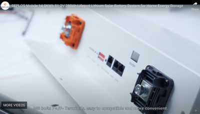
The Mason 280L (vertical) use M8 bolts for the terminals, whereas the horizontal version uses (fairly niche) Futronics connectors, available from Fogstar although this crimps on 50mm2 wire. See screenshot for reference to 280L terminals in their promo video.
Looking at the Sunsynk 8.8kW it seems as if it accepts 35mm2 cable and has an M6 terminal (
pages 15 & 16).
Having the 8.8kW inverter means the currents are somewhat larger than are regularly handled. For instance the NH00 sized fused disconnectors are generally rated up to 160A, with NH1 being rated to 250A. https://www.bimblesolar.com/extras/dc-breakers-fuses/dc-fuse-disconnect
It sounds as if you will need 200A fuses since the 8.8kW inverter has a 190A maximum current.
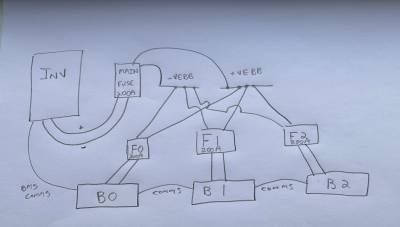
I wired each battery through a 2-pole fuse to a common bus bar, and from that bus bar to the inverter via another 2-pole fuse. This is perhaps overkill, but did ensure an even length of battery connection and avoids the daisy-chain style of connection.
In terms of cabling, I used 50mm2 TWINFLEX up to the per-battery fuse and 25mm2 TWINFLEX for the rest of the connections. The 50mm2 cable was used to get the best crimp to the Futronics connector, but somewhat overkill. Perhaps 35mm2 throughout would be fine.
You will also need ethernet cables (RJ45 etc) to daisy-chain the BMS signal between batteries (if you want BMS communication).
Layout of the batteries is crucial; make sure you know where they will go, have equal length wires and ensure you can route the cables without causing too much stress to the terminals.
Posted by: @chickenbigI have had experience wiring up 2 x Seplos Mason (horizontal) battery boxes to a SunSynk Ecco 5kW.
The Mason 280L (vertical) use M8 bolts for the terminals, whereas the horizontal version uses (fairly niche) Futronics connectors, available from Fogstar although this crimps on 50mm2 wire. See screenshot for reference to 280L terminals in their promo video.
-- Attachment is not available --
Looking at the Sunsynk 8.8kW it seems as if it accepts 35mm2 cable and has an M6 terminal (
pages 15 & 16).
Having the 8.8kW inverter means the currents are somewhat larger than are regularly handled. For instance the NH00 sized fused disconnectors are generally rated up to 160A, with NH1 being rated to 250A. https://www.bimblesolar.com/extras/dc-breakers-fuses/dc-fuse-disconnect
It sounds as if you will need 200A fuses since the 8.8kW inverter has a 190A maximum current.
I wired each battery through a 2-pole fuse to a common bus bar, and from that bus bar to the inverter via another 2-pole fuse. This is perhaps overkill, but did ensure an even length of battery connection and avoids the daisy-chain style of connection.
In terms of cabling, I used 50mm2 TWINFLEX up to the per-battery fuse and 25mm2 TWINFLEX for the rest of the connections. The 50mm2 cable was used to get the best crimp to the Futronics connector, but somewhat overkill. Perhaps 35mm2 throughout would be fine.
You will also need ethernet cables (RJ45 etc) to daisy-chain the BMS signal between batteries (if you want BMS communication).
Layout of the batteries is crucial; make sure you know where they will go, have equal length wires and ensure you can route the cables without causing too much stress to the terminals.
Thanks for that. Could you provide any pictures of your setup? Also what "yield" in KwH are you getting after losses? I may be going overkill with the 8.8
Kind regards
Stew
I bought a Seplos Mason 280L kit. The instructions were not that great - I ended up "inventing" a couple of details that were not in the instructions:
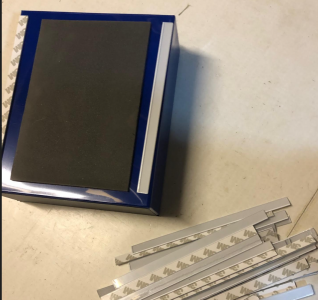
The cells are separated from each other with foam pads. There are also a lot of thin rigid spacers, which are thinner than uncompressed foam pads. The Seplos instructions don't mention these parts - and they also show bigger foam pads on the cells. After much consideration, I fitted these to the cells as the pic below - thinking that as the cells expand, it is only the central foam area that expands. I may have this wrong!?
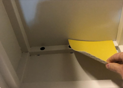
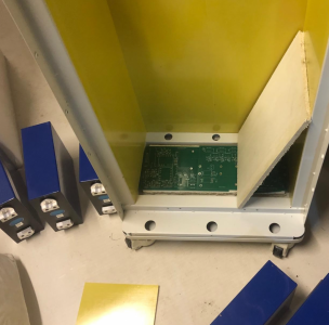
Also - the bottom of our Seplos box is not flat due to the bracing. If cells are directly placed there, they will not receive support centrally, but will only be supported at either end.
I found some incompressible material that I could use to make the bottom flat, and then put a "shelf" on top. I used 2 layers of Magnesium Oxide board and a couple of blank pcbs to make a level surface. Then another layer of MgO board on top, to make a sturdy shelf. MgO is brilliant by the way - similar to plasterboard in that is can't burn, but it's also water resistant and tough. I will email fogstar - I suspect there is a bit of missing metalwork from my kit. It wasn't mentioned in the instructions either though 🙁
A bit more research and I think i need the following:
Posted by: @roblI suspect there is a bit of missing metalwork from my kit.
Strangely I think it is the design to have bare strut-work. At least Seplos' product video shows that to be so. This was one of the reasons I went with the horizontal battery box, albeit at the cost of having to use the Futronics connector and associated bother.
Posted by: @makia20233x 50mm2 cabling between battery packs6x M8 crimp lugs3x 50mm2 cabling between batteries and DC fused isolator2x m8 crimp lugs2x 50mm2 cabling between DC isolator and inverter2x m10 crimp lugs
I may be missing something but 35mm2 cable is probably sufficient somewhat more flexible and less costly. Moreover sticking to one cable size means you only need to order M6 x 35mm and M8 x 35mm crimp lugs, and you can over-order them for when something goes not crimp well.
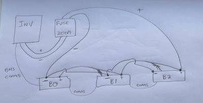
Correct me if I'm wrong but it seems as if you're proposing a solution that daisy-chain the three batteries together without any fuses. This may not be ideal, but perhaps you're happy with that. Note that the +ve and -ve connections are on the opposite battery to try and ensure the voltage drop is experienced evenly by all batteries (so contribute equally to charge/discharge). You will have to ensure good contact when stacking two crimp lugs on a single battery terminal, but this may only be slightly more difficult than one lug.
The system I've installed is a two battery variation of the following.
It does protect individual batteries from faults in others, and also allows for a single battery to be disconnected (by throwing the disconnector), albeit ignoring BMS communication. However it is more complex (4 fuse disconnectors plus bus bars).
Posted by: @makia2023Thanks for that. Could you provide any pictures of your setup? Also what "yield" in KwH are you getting after losses? I may be going overkill with the 8.8
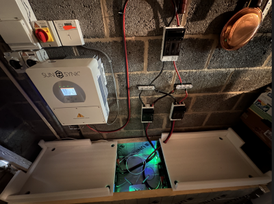
This is the setup, in a garage well away from people traffic. I've used 50mm insulation to try and take the edge off the cold weather. You can see the 50mm2 cable combined with having to change orientation made my life difficult. Perhaps the twin cable was not the best idea!
I'm not sure what you mean by the "yield". The system is currently well over-specced (5kW with about 6.48kW PV on the roof), and I am disappointed with Sunsynk as their Octopus Flux integration still does not work, leaving the battery at > 85% SoC since it was installed. Their servers may be getting upgraded in the next month or so, although that was the story last month. It is rather poor form to get eFixx to advertise this feature when it is still unavailable! I would find the integration useful to earn more money as well as to keep the batteries warm overnight (from discharging between 1600 and 1900 as we as charging up using off-peak electricity).
Neat install !
I've now seen a construction vid from Seplos of the 280L. They don't directly show the base while filling it with cells - I bet it's an embarrasment to them! But it's clear they didn't have any more bits to fit there - so the bottom isn't flat. 😣
Have you managed to get the Seplos communicating with Sunsynk?
Regular RJ45 cable? Any changes to the bms?
I have a 3.6kW Sunsynk (had intended a bigger one, but this one was "spare" and I think probably big enough for us), I'll be connecting it up in the next few days.
Thanks!
Posted by: @roblHave you managed to get the Seplos communicating with Sunsynk?
Regular RJ45 cable?
Any changes to the bms?
I have a 3.6kW Sunsynk (had intended a bigger one, but this one was "spare" and I think probably big enough for us), I'll be connecting it up in the next few days.
The process of getting the Sunsynk inverter to work with the batteries was fraught, but this was because the installer had selected the "Octopus Agile" valuation method which meant the battery was charging/discharging according to what a server commanded rather than what I wanted (and I was unable to change the valuation method because the installer had not given me permission to change settings in the Sunsynk cloud). https://renewableheatinghub.co.uk/forums/energy-storage/my-experience-with-the-selpos-mason-diy-kit/paged/13#post-20361 etc for the series of posts getting more/less confused as time went by.
The connection between inverter and BMS was with the yellow cable that came with the inverter; this is not shown in the above photo because I was still trying to diagnose the charge/discharge issue.
I think I set the inverter to CAN Protocol 0 and limited the charge/discharge current. As for the BMS I can't remember the protocol settings (suspect it was something like Pylontech which might be the default).
Good luck with your installation!
I applied online to Sunsynk to be a user. Once you have user name and password, you can request a status upgrade - I chose "installer", which means I can setup the inverter how I see fit, given it's a diy install. There's a level above this which allows firmware upgrades - they won't allow this without checking you know what you're doing!
Alternatively your installer can probably raise your status to "advanced user". Here's a link:
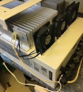
A bit of bodgineering below - the 3.6kW sunsynk hasn't got an external fan, so tends to get pretty hot when working hard. Its big brother that I'd originally planned on does have extra fans. I've glued on 3 low power fans to it, and a 40C bimetallic thermal switch - I used "fixall" type gap filling glue - hopefully it will all come off if I had to make it "as new" for some reason. The fans will be below the heatsink, blowing upwards. There's lots of gaps everywhere so that natural convection can still do something if the fans are off. If it works well I'll maybe fix it in place better.
- 26 Forums
- 2,418 Topics
- 54.8 K Posts
- 335 Online
- 6,098 Members
Join Us!
Worth Watching
Latest Posts
-
RE: GSHP WOES! Midland based engineer recommendations?
@johnbroome perhaps, does it rise in pressure when heat...
By ASHP-BOBBA , 31 minutes ago
-
RE: Ecodan Pump Issues… Circulation pump turns off when heat pump compressor turns off
can you see here it not like a set of steps every 20 mi...
By ASHP-BOBBA , 33 minutes ago
-
So I hear the export MPAN that UKPN assigned should be ...
By Batpred , 2 hours ago
-
RE: Recommended home battery inverters + regulatory matters - help requested
From what I read, the Solis has a very long list of err...
By Batpred , 2 hours ago
-
RE: Ideal HP290 14kW ASHP - how to optimise
Roughly this should cost you £250-£300 per peak month a...
By ASHP-BOBBA , 3 hours ago
-
RE: Installer Fitted 9kW Instead of 11kW Heat Pump and Changed MCS Paperwork - What do I do?
@jamespa thank you again. I know using the offset to tr...
By MairiA , 4 hours ago
-
RE: New Daikin 11kW Altherma 3M install - is it working as it should?
@toodles Thank you for your input. As the days have got...
By Synthbuilder , 7 hours ago
-
RE: Advice for a novice on Mitsubishi Ecodan 6kW
Frost Protect/Freeze Stat is an operation mode, where D...
By F1p , 7 hours ago
-
RE: Fan unit Making terrible noise HELP!!
@gutoffowc Oh no, sorry to hear that, are you in the Ke...
By ASHP-BOBBA , 9 hours ago
-

RE: Sunsynk Whole House Backup Issue
@sheriff-fatman - could you please re-post that in the ...
By Transparent , 9 hours ago
-
RE: Running my new Nibe ASHP efficiently
I didn't. I spent a while manually messing around with ...
By jamieheatpumpnew , 11 hours ago
-
RE: I’m glad the cold spell is over!
I comparison with the 65kWh used above yesterday was on...
By Judith , 11 hours ago
-
RE: Octopus Cosy 12 Heat Pump Regret: Incredibly Loud, Poor Heating & Constant Hum - Help!
I should think so, I thought that pretty much universal...
By JamesPa , 12 hours ago
-

RE: Setback savings - fact or fiction?
I'm also inclined to look into how a defrost is actuall...
By cathodeRay , 12 hours ago
-
MLCP (Multi-Layer Composite Pipe) for ASHP
@editor nope. The info you reported was sufficient for ...
By iotum , 23 hours ago
-
RE: Experience - New Build / Complete New Heating System
@vincro I would be surprised if it is much above 5 to 6...
By ASHP-BOBBA , 24 hours ago
-
RE: Post-Traumatic Heat Pump Stress Disorder
Yes bang on and maybe I can illustrate that by way of e...
By iotum , 1 day ago
-

