Bivalent (or even trivalent!) system design options for a new GSHP installation
@algienon, I know pretty much nothing about bivalent systems so will leave any commenting to others more capable here. However, I do know a fair bit from both sides of the table about scoping out a body of work to be done and getting people to do it so I'm going to provide my two penn'orth on one particular sentence you wrote which caught my eye.
Posted by: @algienon...
My issue comes in finding someone to design a system that doesn't completely abandon what we already have. I'm not precious about all the kit, but the principle of having back-up heating and HW is a must.
...
Ultimately the question needing to be answered is "what are you trying to achieve?"
From everything you have described, you are simply after a cost effective way of dealing with your house's heating needs that is based around renewable energy, but with a backup plan for when you experience occasional but inevitable lengthy power outages. However, by saying you don't want a prospective installer to abandon what you already have you are intrinsically starting to encroach on how the solution should be designed and that's their job to figure out, not yours. If an installer provided a design and quote that could provide exactly what you're after and the design involved ripping everything out and starting again for less than the cost of incorporating your existing kit into a bivalent system, the sentence I've picked out as your quote would eliminate that supplier from your shortlist; I'm not even sure you'd read the detail far enough to get to the bottom line.
You're absolutely right that finding someone competent to design what you want is going to be challenging. I'm also convinced that the someone you need is not only someone who is very experienced but also someone who will listen. That, I suspect, means someone whose first submitted design will not be perfect. However, I also suspect that it means someone who will be able to justify the choices they have made within that design and enter into a round of discussing that design and amending it until the inevitable compromises are ones you, not they, are comfortable with. In order to find that someone, I, in your situation, would concentrate more on telling them what I want to achieve and steer much clearer away from suggesting anything about how I expect the actual solution to look. After all, if they can't convince you with what they suggest, they're not going to get the business anyway.
105 m2 bungalow in South East England
Mitsubishi Ecodan 8.5 kW air source heat pump
18 x 360W solar panels
1 x 6 kW GroWatt battery and SPH5000 inverter
1 x Myenergi Zappi
1 x VW ID3
Raised beds for home-grown veg and chickens for eggs
"Semper in excretia; sumus solum profundum variat"
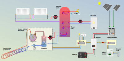
Just parking the detail of the storage battery issue to one side for the moment, I'd like to rebuild @algienon 's last post into something my brain can cope with.
That's called a diagram!
This first attempt won't be 'correct', but the textual description suggests to me that Algie's system is heading in this direction:
Please feel free to print out the diagram and make alterations.
You can then take a photo of that and re-post here.
Or, if you want to play with the original drawing, I construct them using LibreOffice, which is obviously free and multi-platform.
I can send the file by email.
Save energy... recycle electrons!
Thanks @transparent, the diagram looks like a good start to get the design principles for our system sorted. A few questions...
- You have put the thermal store at the heart of the heating system - I've had one installer tell me that this won't work due to the different operating temps of the oil boiler and the GSHP. How do you envisage this working?
- The oil boiler could be sacrificed for a more efficient heat pump system. I'm not precious either way, but I know that added complexity makes a system harder to maintain and operate.
- Where would you see the boiler stove being added?
- Is it worth adding a solar diverter to an immersion in the thermal store so that unused electrons that can't be stored can at least be converted to useful heat?
The thermal store and oil boiler were installed in a new, strengthened plant room built in the loft. This seemed like a great way of freeing up space downstairs, but in hindsight, it is a real pain to get new equipment in and out of the plant room. The thermal store is only leaving if we break it up or remove the roof, and getting a heat pump in will be difficult. There's no space for lifting gear to get it through the loft hatch (if it fitted), so it would have to go on its side through a loft window in the gable end wall, which I've been told is inadvisable as the refrigerant might not resettle correctly. I'm currently considering knocking together two built-in wardrobes to create a new plant room. This would also put the heat pump right next to the area where the borehole will likely go. Is there a rough sizing guide for how big this new plant room would have to be to house a GSHP, water tank and all the other gubbins?
Could we install a separate DHW tank beside the GSHP in the new plant room and run the thermal store for the heating at the optimum temperature for the GSHP? One advantage of this is that the plumbing for the heating is already in place. Could the oil boiler then be used to top up the thermal store if it gets below a certain temperature outside so that the GSHP doesn't have to work so hard against the heat loss from the building? The boiler stove has little in the way of temperature control, but could that be used when it gets cold out? I don't know what feedback is required from the thermal store to the heat pump to tell it if more heat is required, but if either the oil boiler or boiler store is in operation, I'm guessing the heat pump will effectively turn off.
As I see it, I have at least four groups of problems to solve:
- Site - where does the GSHP go?
- What equipment goes and what do I need to buy (lose the oil boiler, get a dedicated DHW tank?)
- Plumbing - how does this all get connected up
- Control system - what decides which source is providing the heat
I'm beginning to understand why people find it impossible to switch from gas to heat pump. It's not easy and takes time. 90% of all boiler replacements are distressed purchases (the boiler has died), and people can't wait to get a heat pump system designed for them when the family is cold
If you can post the diagram file, it might be easier for me to update it with some of my thoughts.
Posted by: @transparentJust parking the detail of the storage battery issue to one side for the moment,
Unparking the battery question again 😀, as I'm likely to proceed with this in the near future - assuming I can get a design sorted.
I currently have 18 PV panels (6 kW) on a south-facing roof. 12 are connected to a 3.6 kW Solis inverter which is situated in a room in the loft that is almost directly above the consumer unit in the room below. I need to get the other 6 connected and the roof has space for another 6.
As an aside, quite terrifyingly, I have more background (but not answers) as to why my panels are not exporting and the inverter looks to be dead. The inside of the DC isolator switch from the panels to the inverter is coated in black soot! The electrician is coming tomorrow to work out why and replace the inverter. I suspect we are very lucky not to have had a house fire! There's no heat or smoke detector in that room. This will be rectified tomorrow.
Going back to my requirements from the previous page...
- Use all I generate
- If it's not used at the point of generation, then it is stored in the battery for later use
- If the battery is at capacity, it is diverted to water heating. A heat pump will be more cost-effective, but if the electrons are going to waste anyway, they may as well be put to use
- At some point we'll undoubtedly end up with an EV, so it will either fit between 1 and 2 or 2 and 3
- Be able to island the system so that we can run a few small devices, charge phones and use lights when we have another power cut
And @transparent's diagrams, are we looking at
- A string combiner to combine two arrays of 12 panels
- Feeding an inverter that can cope with 8 kW peak
- The inverter
- passes through the DC from the panels to a battery
- converts the mains AC to DC and stores it in the battery
- passes through the mains AC when the battery is discharged
- feeds the house circuits with 230V AC, whether it's from the mains or PV
This seems like a very clever piece of kit. Any make and model recommendations that I can research? Can this prevent PV generation from being exported back to the grid during a power cut?
I'm assuming the picture of a consumer unit between the mains AC and inverter is, in actuality, some form of protection that will trip to protect the system and that the red button after it is for isolating the system from the mains for maintenance?
I don't want the battery anywhere near the house, most certainly not in the loft room. I'm considering putting it in the garage. Which is about 10 metres from the consumer unit. Are there recommended maximum runs of DC and AC cable that I need to be aware of? Should the inverter be in the garage too? This would put the PV panels about 20 to 25 meters away from the inverter.
Posted by: @algienonThe inside of the DC isolator switch from the panels to the inverter is coated in black soot! The electrician is coming tomorrow to work out why and replace the inverter.
This will be rectified tomorrow.
As it's DC, then it's already rectified 😉
Sorry. It's past my bed-time....
Save energy... recycle electrons!
@transparent You are a bright spark aren’t you?!
Toodles, heats his home with cold draughts and cooks food with magnets.
After 3 days, I'm now returning to this topic and the plethora of points made by @algienon
Posted by: @algienon
- You have put the thermal store at the heart of the heating system - I've had one installer tell me that this won't work due to the different operating temps of the oil boiler and the GSHP. How do you envisage this working?
Well, I hadn't intended that particular 1st edition of the diagram to be taken completely literally.
It simply presents the available set of options which have cropped up in this topic to date.
But you should note that I've placed the input coil from the oil boiler halfway up the thermal store, whilst the coil from the GSHP is at the bottom.
IOW I'm indicating that a thermal store has a temperature gradient within it, which needs to be taken into account.
If the input temperature from the oil boiler/stove is significantly too high, then there are other solutions which can be engineered.
The same problem is addressed, for example, when someone adds a UHF zone in a house where the C/H circuit elsewhere is radiators.
The usual solution in that scenario is a thermostatic mixer valve, which blends the incoming C/H water with a portion of that from the UFH return side.
Posted by: @algienonThe thermal store and oil boiler were installed in a new, strengthened plant room built in the loft.
Oh! Well that's going to create another interesting sub-set of problems.
You certainly wouldn't want to locate a HP up there as well!
I'm intrigued however, about that loft-space.
Is it within the heated element of the house?
Ie do you have a 'warm roof' construction, whereby the insulation layer is between and on top of the rafters?
The description of your roof and potential for solar panels is useful.
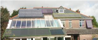
On the basis of 'I'll show you mine and you show me yours', here's what I currently have on the south elevation:
You will see that I also a 30-tube solar-thermal array at the lower roof level, which is an input to my thermal store.
I also have a nominal 24v DC immersion heater in the thermal store, which was designed-in to act as a dump-load for a wind-turbine.
That turbine caught fire a number of years ago, and has yet to work its way to the top of my ToDo list.
But I don't have a solar diverter, and others have commented both for and against on other topics here.
I suggest you read those threads first.
Posted by: @algienonThe inside of the DC isolator switch from the panels to the inverter is coated in black soot! The electrician is coming tomorrow to work out why and replace the inverter. I suspect we are very lucky not to have had a house fire! There's no heat or smoke detector in that room. This will be rectified tomorrow.
What's the update on this DC isolator?
Do you have any photos of it, either whole or taken apart?
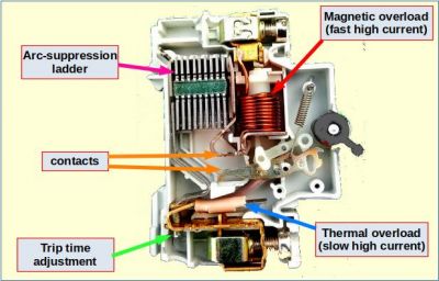
It should look something like this inside, although I've removed a few parts from the model in this pic to aid clarity:
For a DC-breaker, the arc-suppression ladder usually has a higher number of plates, and there are magnets either side of the contacts.
Those small magnets pull the arc into the ladder when the contacts open, using Flemings Left-hand Rule and some rusty science from Year-8.
For that reason a DC trip has a polarity, and must be connected the right way around in the circuit.
If not, the magnets will push the arc into the contacts when they open, resulting in their vapourisation.
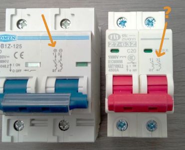
The breaker on the right with the red actuator has the correct symbol for one that is for DC use, but no polarity indicated on it.
So it's 50/50 as to whether it will weld its contacts together under fault conditions!
May I stop for a moment and let you digest these points?
You will begin to realise that the number of issues you are raising in each of your two previous posts are sufficient to keep me writing all day!
Can we try to focus on what you need to understand in general, before we plunge deeper into the underlying physics?
Save energy... recycle electrons!
Let me pick up other two top-level questions.
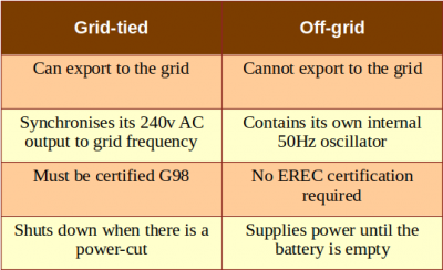
1: We need to understand the difference between a grid-tied inverter and an off-grid inverter, because that addresses the following points:
Posted by: @algienon
- The inverter
- passes through the DC from the panels to a battery
- converts the mains AC to DC and stores it in the battery
- passes through the mains AC when the battery is discharged
- feeds the house circuits with 230V AC, whether it's from the mains or PV
This seems like a very clever piece of kit. Any make and model recommendations that I can research? Can this prevent PV generation from being exported back to the grid during a power cut?
There are two main types of inverter which can take input from the grid and solar panels...
The third line is the key point.... Where does the 50Hz come from?
SunSynk inverters are an exception to this.
They can export to the grid, but also have their own internal oscillator which still operates during a power-cut.
But you are then left to decide which of your household circuits are to be supplied from that "backup" connection.
Posted by: @algienonI don't want the battery anywhere near the house, most certainly not in the loft room. I'm considering putting it in the garage. Which is about 10 metres from the consumer unit. Are there recommended maximum runs of DC and AC cable that I need to be aware of? Should the inverter be in the garage too?
There is a new BSI standard which addresses this issue.
We've discussed PAS-63100:2024 on another forum topic.
I'm unhappy with that new 'standard' for a number of reasons, which I've communicated to BSI.
- it addresses fire safety for battery installations, but lumps together all types of cell containing lithium as a single group
- it doesn't address good/bad system design, nor safety of the devices or personnel during installation & maintenance
- it doesn't address 'security' of supply, either from the viewpoint of the householder or the grid
BSI have just responded last week to say that those points "fall outside of the scope for PAS-63100".
Yes, I knew that.
That's why I wrote to highlight what wasn't being included!
PAS-63100 isn't mandatory...
... until the first house with a storage battery catches fire, at which point the house insurers will insist on it!
Even so, it is generally the case that batteries shouldn't be in the loft (PAS-63100 section 6.5.5).
What they fail to mention is that the inverter shouldn't be there either.
If there is fault within the inverter's electronics which causes a near short-circuit, then lots of amps will flow from the battery.
The battery doesn't mind that.
It's a natural consequence of its chemistry.
The inverter, however, is likely to catch fire because all that energy gets converted to heat.
An installer could abide by the recommendations of PAS-63100, and give you a pretty certificate to state that it complies.
But the house could still catch fire. 😲
I'm not happy with that.
I'm surprised that BSI is.
And I'm not going to leave matters as they are.
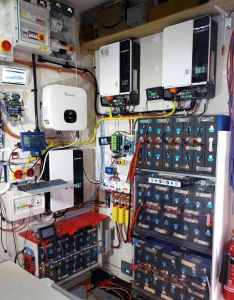
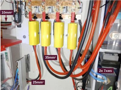
2: To give you an idea about proximity of consumer units, inverters and batteries...
does this help?
The consumer unit(s) are just out of shot to the left.
But they could be further away. You'd just need longer copper wire to make the connections, which increases the price.
DC cables between batteries and inverters are chunky and cost a lot more.
They will typically be rated for 100A continuous current, which equates to 5kW for a nominal 50v battery.
Save energy... recycle electrons!
Wow! Huge amount of info. Thanks for taking the time.
I'm off to bed, but I'll give this the attention it needs tomorrow.
Right, back to the topic at hand. To answer some of your questions first
Posted by: @transparentI'm intrigued however, about that loft-space.
Is it within the heated element of the house?
Yes, the floor of the plant room is uninsulated, while the walls and ceiling are super-insulated. When the architect proposed it, putting the plant room in the loft seemed like a genius idea to free up space downstairs. In hindsight, it makes any changes an absolute pain.
Posted by: @transparentOn the basis of 'I'll show you mine and you show me yours',
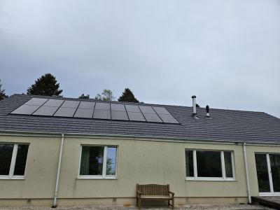
Here's a picture of my PV array and the inverter (which is in the loft, but not the plant room). The plant room is directly below the smaller flue on the right. The left-hand flue is the boiler stove. The roof is south-facing and has a pitch of 35 degrees
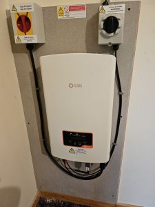
I don't have any pictures of inside the DC isolator, but it was completely covered in soot. The electrician was here on Thursday. He replaced the DC isolator with a new one. The original was the same brand as the AC isolator. The inverter was swapped out too, as it was completely dead. It is being sent back to the manufacturer to see if they can find out why. The room with the inverter now has a smoke alarm fitted, as I think we were very lucky not to have had the house burn down. The next phase of the project will see the inverter moved outside!
So, to focus on what I need to know...
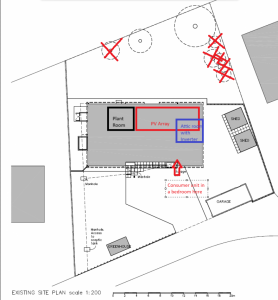
The priority will be to upgrade the PV system to include storage. I've attached plan of the garden to show where everything is (hopefully you can view it larger than I can manage to paste it in!)
The garage is dry-ish (rain blows in under the door, but the electrics would be on the wall anyway), and the bottom shed is insulated and lined with plywood on the inside. I'd have to remove storage shelves from the shed It might be the best place for the battery and inverters but I'm not sure if there is enough wall space if I look at the space your set up takes.
Questions
- How far can I run DC cable?
- How deep does the trench need to be?
- Can AC and DC be in the same trench? If so, any separation issues?
- If I understand correctly, it sounds like the inverter should be with the battery, i) because it gets a fire hazard out of the house, and ii) it minimises the length of the expensive DC cable between the battery and the inverter.
I'll stop there for the moment. Don't want to have too many questions in one post 🙂
Posted by: @algienonI don't have any pictures of inside the DC isolator, but it was completely covered in soot.
What about pictures of the outside?
I've been testing DC breakers, trips and rotary isolators from different manufacturers, and I'd like to know which company made the one which failed on your site if possible.
Is the 'isolator' which was replaced, the rotating-knob unit at top right of your backing board (C&D?)?
Has the installer used the same product for the replacement unit?
Or was the original one a red/yellow rotary isolator which was designed for AC/mains ?
Those photos and plan are just what we need to see.
So I now realise that you're in a bungalow with tall trees nearby.
That significantly reduces the risk of lightning strikes on your rooftop panels.
You have no fuses or trips on the (4mm) down-leads from the PV panels.
That's OK. There's no mandatory 'specification' for this part of an installation.
I think there should be...
... and it would make sense to have it within the same "Installation Guidance" document as addresses battery storage.
These two technologies are increasingly being regarded by homeowners as a 'matched pair'.
Location & Layout
I posted that photo of my own installation so that you could get an idea of the sort of volume/space required to house batteries and inverters.
I do have an EV, but the Charger Point can't take power from the in-house storage batteries.
The EV is a VW ID3, and has a usable capacity of 58kWh.
The four 'house' battery banks are 14kWh each, giving a total of 56kWh.
If you want to hold enough electricity to re-charge an EV from the house batteries, you are facing a large-scale installation!
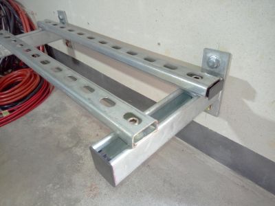
I'm happy building my own steel racking, bolted to the wall behind...
... and then running the battery cables myself.
As this is 52v, it can all be done without a qualified electrician.
Many others here start with a Seplos Mason box, or similar.
This is a steel container with all the wires and Battery Management System (BMS), into which you place the LiFePO4 cells.
There's lots of discussion and photos of the Mason strategy over on another topic.
There's another (rival) DIY battery box available from Fogstar, which is being discussed here.
These solutions are using 280Ah LiFePO4 cells - 16 in series to provide around 52v DC
The final weight is over 100Kg per battery, which is why you have to put them together on site.
If you opt to have a professional installer provide battery boxes and cable them together, then they will be specifying units which they can carry.
That Health & Safety limit is 25Kg, for which you would expect to get 4kWh - 5kWh of storage capacity.
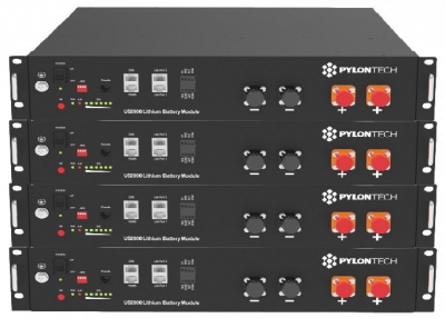
Many installers like the Pylontech boxes, which can be mounted into a standard 19-inch rack.
But the cost per kWh of storage is now 4x the DIY approach I first mentioned above!
Fogstar is a reputable UK supplier.
And you can also buy 280Ah LiFePO4 cells direct from China, which is what I've been doing.
The present rate is about $70 (US) per cell, plus shipping and VAT, which the courier handles for you.
Posted by: @algienon
- How far can I run DC cable?
- How deep does the trench need to be?
- Can AC and DC be in the same trench? If so, any separation issues?
- If I understand correctly, it sounds like the inverter should be with the battery, i) because it gets a fire hazard out of the house, and ii) it minimises the length of the expensive DC cable between the battery and the inverter.
There are no absolute limits to DC cable length.
To reduce the voltage drop you can use a thicker cable of course... which costs more.
I've deliberately used different sizes/lengths of battery cable so that I can get a sense of the effect it makes.
To get an idea of cable prices, go to 12-volt Planet.
Trench depth isn't stipulated for low-volt cables.
But wouldn't you be running the 500v solar output in one direction, and 240v AC back to the house?
Ie the inverters and batteries are all together in the external store/garage.
The golden rule is to go two spade-depths deep for any cabling that runs below a surface which could be dug.
You then cover the cables/trunking with 100mm of sand/soil, and place an Electrical Warning tape on top of that.
Anyone digging there in future will find the tape before the cables!
Save energy... recycle electrons!
For your interest @algienon this is what happens when a 'professional' contractor doesn't bury 440v 3-phase cables deep enough:
The large black box is a cable joint installed by National Grid, who had to come and sort out a shallow cable running across the front of a new-build house.
The sub-contractor also damaged the cable when it was laid, thereby allowing water to pass inside.
That weak-spot then got hot when the current being drawn by the attached houses reached a peak... and exploded within the ground due to a breakdown of the inner insulation.
Most of the larger housing developers use an IDNO (Independent Distribution Network Operator) rather than paying the standard rate of the DNO who holds the regional licence. The IDNO will often allow the Developer to save even more money by them digging the trenches themselves. Since cable depth on the grid side of our meters isn't specified within the regulations, they scrape the ground with a back-hoe rather than properly dig out a trench 600mm deep.
Of course, if you were to do this with a private SWA mains cable running within your garden, then an electrician would be telling you he can't certify the work because it breaches the IET rules. 😥
Save energy... recycle electrons!
- 26 Forums
- 2,396 Topics
- 54.3 K Posts
- 265 Online
- 6,077 Members
Join Us!
Worth Watching
Latest Posts
-

RE: Setback savings - fact or fiction?
No need to create a new thread, @sheriff-fatman. You do...
By Majordennisbloodnok , 2 hours ago
-

RE: Power outages and storms: A surprisingly good DNO experience
Well done to Scottish Power for doing a good job. Well ...
By Majordennisbloodnok , 3 hours ago
-
RE: Advice for a novice on Mitsubishi Ecodan 6kW
Fair point. The highest frequency of defrosts I'd seen...
By Sheriff Fatman , 4 hours ago
-

RE: Heatpunk Floor plan issues
It's usually the complete opposite... seldom that Safar...
By Mars , 4 hours ago
-
RE: RDSAP10 effect on existing heat pump EPC rating?
@mike-patrick interesting update - thanks.I've been thr...
By Tim441 , 5 hours ago
-
RE: Recommended home battery inverters + regulatory matters - help requested
I remember reading in some inverters. They mandate a se...
By Batpred , 5 hours ago
-

RE: Fan is clipping ice build up from the front of unit.
@majordennisbloodnok I’ll not go there thanks! Toodles.
By Toodles , 7 hours ago
-

RE: Running from backup generaor in powercut?
@majordennisbloodnok Back in the 80’ or 90’ we had a te...
By Toodles , 7 hours ago
-
RE: Running my new Nibe ASHP efficiently
I'm new to the forum. Did you get a reply to this last ...
By Mike @ Camelot , 8 hours ago
-

RE: ASHP Energy Consumption: Aira 12kW heat pump
@grantmethestrength MCS requirements for DHW capacity h...
By Toodles , 9 hours ago
-
RE: New Mitsubishi Ecodan 11.2kW installation - L9 errors and maybe more
Great to hear! I just figured this out a day or tw...
By anotherdaveuk , 10 hours ago
-
RE: Help me keep the faith with my air source heat pump installation
@adamk I'm observing my own system at low temperatures ...
By dr_dongle , 15 hours ago
-

RE: Free Ecoheat Heat Pump Install
@deltona Yes older houses are problematic like that, bu...
By bontwoody , 1 day ago
-
RE: Radiator sizing sanity check
As I mentioned early on the cost of supplying and fitti...
By JamesPa , 2 days ago
-
RE: Electricity price predictions
Great point, one of the key ones in my chat with Octopu...
By Batpred , 2 days ago
-

RE: New Fogstar 15.5kWh upright solution
Let me point out that there are many Chinese suppliers ...
By Transparent , 2 days ago
-

RE: Weather compensation- why you should use it
@majordennisbloodnok — The Two Ronnies Mastermind sketc...
By cathodeRay , 2 days ago
-
Just realised that this image of the cylinder cupboard ...
By Sheriff Fatman , 2 days ago
-

RE: Rodents! A word of warning for heat pump owners
Two thoughts: 1: Let's ask @david-s if Primary Pro in...
By Transparent , 2 days ago
-
RE: Solis S6-EH1P8K-L-PLUS – Why I Chose It and What I’ve Learned So Far
In the diagram below, I describe my understanding of th...
By Batpred , 2 days ago

