Is this a bad installation and is there something wrong with my Samsung heat pump?
Posted by: @david999Also thinking that if the pump initiated a defrost is the room stat shutting the pump down and causing the ice before it defrosts it
I am in the process of compiling a more detail reply, but could you confirm if your heat pump is operating in Weather Compensation (WC) mode or not?
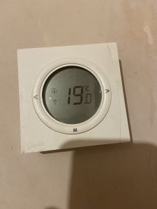
@derek-m it was adjusted slightly as far as I’m aware but no idea if it’s activated. Not sure if this room stat is suitable or if it’s wired like a conventional boiler cycling on and off.
Posted by: @david999@derek-m mechanical electrical. My good friend has two degrees in pumps and gas turbines but not good on heating systems.
I read the other post and at the minute my heat pump is cycling because of the room stat and in one position too warm leaving rooms cold and the other way in the cold rooms leaving me too warm. If it was working like a conventional boiler then it would shut down on the room stat providing it’s positioned in the correct place and cycle on demand.. but I’m hearing that perhaps this shouldn’t happen and the pump should run all the time and confused how I would regulate heat.
To answer the last question first, the heat pump controller should regulate the Indoor Air Temperature (IAT) using Weather Compensation (WC), which I will explain in more detail later if necessary.
You should have been provided with heat loss calculations for your home, which should detail the room by room heat loss with an Outside Air Temperature (OAT) in the region of -2C or -3C.
To maintain a constant IAT in any given room, it is necessary for the heat emitters to emit the required quantity of thermal energy that will match the heat loss at the present OAT. If the heat loss from a particular room is say 1200W at an IAT of 21C and an OAT of -3C, then for each 1C change in temperature difference between IAT and OAT, the heat loss will change by 50W, so at an OAT of 9C the heat loss will be in the region of 600W.
If the heat emitters are radiators, the quantity of thermal energy that they will emit will primarily be dependent upon the difference between the Average Water Temperature (AWT) within the radiator and the IAT. I always find examples to be of use so consider the following:-
If the above mentioned room has a heat loss of 1200W at an OAT of -3C and contains two radiators with a specified output capacity of 1600W each at the standard DT50, giving a total heating capacity of 3200W, what would be the required AWT to keep the IAT at 21C?
Using the attached spreadsheet it gives an AWT value of 44.51C.
The water coming out of a heat pump, Leaving Water Temperature (LWT), is normally in the region of 5C higher than the water going back to the heat pump, Return Water Temperature (RWT), so the AWT at the radiators would be approximately half way between the two. To produce a AWT of 44.51C would therefore require a LWT of 47C and a RWT of 42C.
By now you are probably thinking what on earth has all this got to do with my heat pump freezing up, some rooms being too warm and others being too cold. A great deal.
I would suggest that you start by obtaining a copy of the relevant installation manual for your system and familiarising yourself with how how to navigate the different menu's within the controller and note the settings of your system, particularly the settings of the WC curve and whether it is enabled or disabled.
Hopefully other Samsung owner's may be able to guide you to the required data.
Once you have established whether your system is in WC mode and its settings then come back with the details.
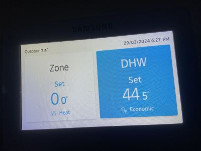
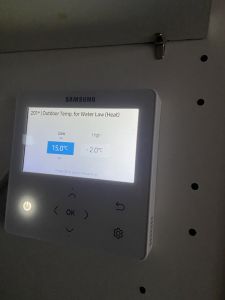
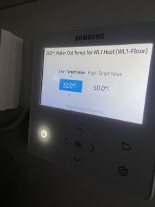
If my understanding is correct your system is operating in WC mode with settings of a LWT of 50C at an OAT of -2C and a LWT of 32C at an OAT of 15C. These values seem reasonable though they may need to be optimised.
I would therefore suggest that at a convenient time you open all the TRV's fully, except for used bedrooms and allow all the room temperatures to stabilise. Any room thermostats should also be set to a temperature of 1C or 2C above the desired value to ensure that the heat pump is operating as much as possible. Also check that the lockshield valves on the radiators are also fully open.
Find out which room has the lowest temperature and if necessary adjust the WC settings to raise or lower the LWT to bring this room temperature to the desired value.
Starting at the warmest room, gradually close the lockshield valves on any radiators to lower the IAT to the desired value. Note, this is not a 5 minute job and could potentially take hours or even days to achieve. Once the temperature in the warmest room has been balanced carryout the same procedure in the next warmest room, and so on and so forth.
Adjusting lockshield valves in one room may affect water flowrates in other rooms so it may be necessary to repeat the balancing process.
Once balancing of the radiators has been accomplished the optimisation of the WC curve can then be completed if necessary.
If after completing the above the heat pump is still suffering severe icing then come back for further help and advice.
There's a wider issue we ought to consider @david999 - how do we impart this knowledge into the wider population of GB (incl the professionals who aren't achieving satisfactory installations)?
We're not suffering from a lack of willingness to move towards eco-friendly technologies.
But every inefficient heat-pump installation has long-term negative outcomes on friends, family and work-colleagues who hear about it.
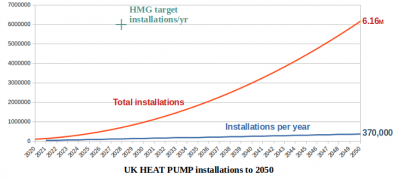
Dept Energy thinks the significant issue is a lack of MCS approved installers who can apply the £7500 grant under the Boiler Upgrade Scheme.
So they are promoting a 3-day course to transform existing plumbers and electricians into Heat-Pump Installers.
They get £500 off the £700 course-fee and can then self-certify their work within the Building Regulations' Competent Persons Scheme.
Do you have an opinion on that strategy?
Save energy... recycle electrons!
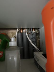
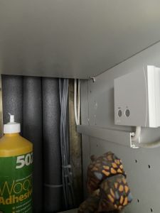
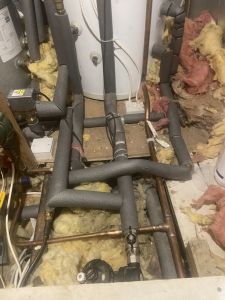
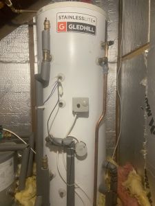
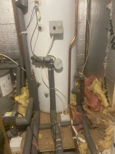
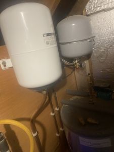
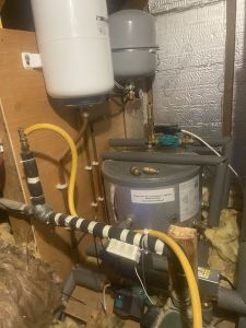
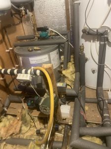
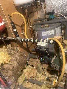
@david999 could you please post some photos of your plant room where your conrtrols, distribution pumps, valves, etc. are located so we can see the pipework and if there’s any zoning?
Get a copy of The Ultimate Guide to Heat Pumps
Subscribe and follow our YouTube channel!
@editor I wasn’t going to trouble you guys again you have been so kind and felt I was being a nuisance.
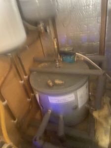
i have attached the photos you requested. I was under the house again really to have a better look at that pipe work as it looks fairly untidy. I noticed no manifolds and feed and return pipes are hard to fathom. I checked in the house to see if there was consistency regarding flow and some feed through the thermostat valves and others through the lock valves. Had it been me I would have fitted manafolds and at least connected all the feeds first so no crossovers. I need to take more photos and try to figure what’s what underneath. So depressing. The stuff in the plant room is too complicated for me and I think for the installers as well.
That is ridiculous. So you have the hot water tank, a buffer tank, a red and a white tank and a big white one as well. For comparison, our installation just has the hot water tank and the small red and white ones, basically for expansion of water and adding more if necessary. Not to mention the pipes everywhere and do I see two water pumps?
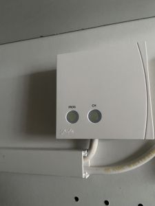
It looks like your Samsung controller is in a cupboard? I believe you can put them out in the room and use the room temp to control the heat pump, which would be better than leaving it in a cupboard.
- 27 Forums
- 2,495 Topics
- 57.8 K Posts
- 552 Online
- 6,220 Members
Join Us!
Worth Watching
Latest Posts
-

RE: Humidity, or lack thereof... is my heat pump making rooms drier?
That’s my pleasure, @andrewj. The only challenge now is...
By Majordennisbloodnok , 7 minutes ago
-
RE: Electricity price predictions
@toodles @skd Then there is not going to be much from t...
By ChandyKris , 52 minutes ago
-
RE: Solis inverters S6-EH1P: pros and cons and battery options
@batpred I reckon Andy might know a thing or 2 about...
By Bash , 1 hour ago
-
RE: What determines the SOC of a battery?
@batpred Ironically you didn't have anything good to...
By Bash , 2 hours ago
-
RE: Testing new controls/monitoring for Midea Clone ASHP
Here’s a current graph showing a bit more info. The set...
By benson , 3 hours ago
-
RE: Setback savings - fact or fiction?
True there is a variation but importantly it's understa...
By RobS , 3 hours ago
-

Below is a better quality image. Does that contain all ...
By trebor12345 , 3 hours ago
-
Sorry to bounce your thread. To put to bed some concern...
By L8Again , 3 hours ago
-

@painter26 — they (the analogue gauges) are subtly diff...
By cathodeRay , 4 hours ago
-
Our Experience installing a heat pump into a Grade 2 Listed stone house
First want to thank everybody who has contributed to th...
By Travellingwave , 7 hours ago
-
RE: Struggling to get CoP above 3 with 6 kw Ecodan ASHP
Welcome to the forums.I assume that you're getting the ...
By Sheriff Fatman , 10 hours ago
-
RE: Say hello and introduce yourself
@editor @kev1964-irl This discussion might be best had ...
By GC61 , 12 hours ago
-

RE: Oversized 10.5kW Grant Aerona Heat Pump on Microbore Pipes and Undersized Rads
@uknick TBH if I were taking the floor up ...
By JamesPa , 1 day ago
-

RE: Getting ready for export with a BESS
I would have not got it if it was that tight
By Batpred , 1 day ago
-
RE: Need help maximising COP of 3.5kW Valiant Aerotherm heat pump
@judith thanks Judith. Confirmation appreciated. The ...
By DavidB , 1 day ago
-

RE: Recommended home battery inverters + regulatory matters - help requested
That makes sense. I thought better to comment in this t...
By Batpred , 1 day ago
-
Bosch CS5800i 7kW replacing Greenstar Junior 28i
My heat pump journey began a couple of years ago when I...
By Slartibartfast , 1 day ago
-

RE: How to control DHW with Honeywell EvoHome on Trianco ActiveAir 5 kW ASHP
The last photo is defrost for sure (or cooling, but pre...
By JamesPa , 1 day ago
-

RE: Plug and play solar. Thoughts?
Essentially, this just needed legislation. In Germany t...
By Batpred , 1 day ago
-
RE: A Smarter Smart Controller from Homely?
@toodles Intentional opening of any warranty “can of wo...
By Papahuhu , 1 day ago
-
RE: Safety update; RCBOs supplying inverters or storage batteries
Thanks @transparent Thankyou for your advic...
By Bash , 2 days ago
-
RE: Air source heat pump roll call – what heat pump brand and model do you have?
Forum Handle: Odd_LionManufacturer: SamsungModel: Samsu...
By Odd_Lion , 2 days ago
-
RE: Configuring third party dongle for Ecodan local control
Well, it was mentioned before in the early pos...
By F1p , 2 days ago

