Posted by: @iantelescopedoes not automatically install PWM controlled
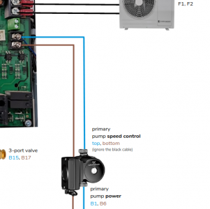
I know that if you buy and install a samsung gen 6 kit from midsummer wholesale a PWM pump is specified and documented in the quick start guide. They also say specifically to ignore the black cable.
full guide here
Hi William,
Many thanks for the info from Midsummer !
I am now convinced that my particular SIG/REF output from my Control PCB is faulty.
I have however finally found a way of testing whither the PWM System is working .
If the Grundfos motors are supplied with a constant 240 vac from Pins B1 and B6 and the PWM is NOT Working then the system will after a 10 minute interval display a E912 ERROR.
If the Grundfos motors are supplied with the switched 240 vac from Pins B7 and B8 and the PWM is either Working OR NOT Working the system will display NO warnings OR ERRORS on either the SAMSUNG OR the GRUNDFOSS Motors. The user will have NO Indication whither the PWM system is working OR NOT.
My Particular system , and I suspect some others, is defaulting to the MAXIMUM MOTOR SPEED giving NO INDICATION of the PWM Status.
I am NOW driving my system from TWO !0 Khz Waves with a 40 % DUTY Cycle setting my Flow rates to 9.4 lpm .
i know that other users will have working PWM Systems ..............
Please give any evidence about the PWM Working or NOT Working ?
ian
@iantelescope I gave you the midsummer wholesale doc several messages back.
B1 and B6 are permanent L/N. when connected to these, the pump will run if the PWM is not working (this is by design, Profile A runs the pump if PWM control is not present), and the samsung system will as you say give an E912 error which is its way of saying "the circulation pump is running and it shouldn't be."
B7 and B8 are switched L/N and are not intended for the PWM configuration of pump. they are for a non-PWM pump setup, where that pump has to be on/off switched using a switched live. If however you mistakenly use these in a PWM setup , you will still get some indication because you will see a change in flow rate during pump run, if PWM control is working and the heat pump decides to change the flow rate. But, its quite clear in the documentation, it shouldn't be setup that way for PWM.
Flow rate is visible within the status information on the controller display , I assume you know how to get to that? that is another indicator of PWM working or not.
It would seem to me that your system's issue is a broken PWM output on the PCB. Whether you choose to fix that with by working around it with an arduino home-build, or warrantying the PCB, is up to you of course, its your system. you've obviously had some considerable grief in getting to the point of being able to prove that, but now that you have got there (With help from this forum), I don't think its appropriate to still keep pointing the finger at the mfrs for lack of documentation. perhaps the point should be is that their help to you in troubleshooting where the fault lies has perhaps been less than ideal? but that's what internet fora are for 😉
IanC
My octopus signup link https://share.octopus.energy/ebony-deer-230
210m2 house, Samsung 16kw Gen6 ASHP Self installed: Single circulation loop , PWM modulating pump.
My public ASHP stats: https://heatpumpmonitor.org/system/view?id=45
11.9kWp of PV
41kWh of Battery storage (3x Powerwall 2)
2x BEVs
My PWM System appears to be faulty.
Following a Visit from a SAMSUNG Engineer , I asked him "why does my PWM System NOT work."
He replied that he was aware that the range of the control output from the Control board resulted in the Motors being constantly driven at Maximum Speed.
My PWM is constantly being driven at maximum speed!
The SAMSUNG Engineer also advised that I consider fitting the Power Relay ( pg 23 of the Manual) in series with the PCB Relay to limit the effects of arcing on the PCB Relay.
Yes, I am sceptical ......but with reason!
ian
Hi William,
With my PWM driver chip not working I have been Controlling Both of my PWM pumps using a Pulse Generator.
The Pulse generator is set to 10 Khz frequency with Duty cycle of 40%.
I have stopped my Hot water system and switched on my 50 litre Volumising tank.
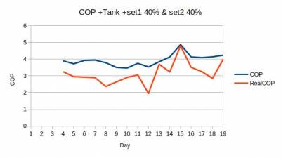
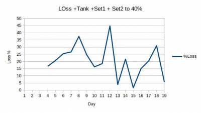
I have measured the resulting COP and REAL COP , REAL COP being the power measured by a water power meter.
The COP & REAL COP are ....................
The Loss between the Heat pump and the Power Water meter....
Both show a n improvement ......but I will average the results over several days before coming to a conclusion.
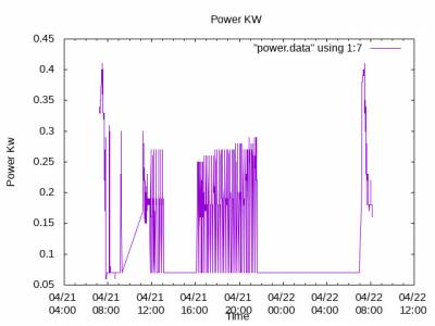
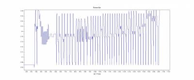
My Power measurements clearly show the continued Hyper-Cycling ........................
So I still have hyper-cycling ......
In close up the cycling is.............
The Cycling time is 21 mins ......an improvement , but I will await several more days of data before cheering too much.
The Noticeable Initial leading edge power pulse is a result of charging the Motor Charging capacitor.
As a visiting SAMSUNG ENGINEER said, "This charging current causes the PCB Relays on the SAMSUNG CONTROL board to Arc , and eventually prematurely fail".
ian
.
@iantelescope I believe the short cycling problem would be rectified by increasing the hysteresis value for the RWT sensor. What is the current setting? What is the prescribed default value.
I know on a Clivet system the default value for dtSH is 2 degrees (adjustable from 1 to 10 degrees in 1 degree increments). If you do increase the value then you do need to think about increasing LWT by at least the same amount.
If you increase dtSH the cycling will decrease notably, if it doesn't then there must be a fault else where.
I wonder what peoples' views are on using a volumiser to reduce cycling. The idea as I understand it is that by increasing the circulating volume (which is all that a volumiser does, it being a passive tank of say 50L added in line to the circuit), both the on and off phases last longer, on longer as there is more fluid to heat, off longer as there is more residual heat to be lost. Seems like a sensible low tech idea to me. It it is placed within the heated part of the house, any heat loss from it isn't really lost, as it contributes heat to the house. Any thoughts/experiences?
Midea 14kW (for now...) ASHP heating both building and DHW
Posted by: @iantelescopeThe Pulse generator is set to 10 Khz frequency with Duty cycle of 40%.
I am not sure why you would run within a PWM frequency outside the defined operating parameters of the pump. Any particular reason you need 10kHz
Posted by: @derek-mIf you want to stop or reduce the cycling, you should consider reducing the LWT.
I have been trying to get to the bottom of the occasional cycling of my heat pump. Once my heat pump gets to its lowest modulation level, I actually have to raise the LWT in order to increase the rate of heat being dissipated by the "radiators" (the dT goes up a little bit when I do this as I have a constant flow rate) this then stops the cycling, of course then the room gets warmer than I want it. I have come to the conclusion that you can't stop the cycling at this point and it is better to switch off the heat pump. I think that if your heat pump is sized correctly [i.e, the entire system is properly engineered] you would not have this issue as you could keep tuning your system without hitting limits.
Mine is a bit oversized for the radiators [but correctly sized for the heat loss @ -2], since I did not change them as the whole house is going to UFH, over time.
Amazingly my 16kW Samsung can modulate down to around 700 watts input [without PWM ... this on my todo list].
This is about
- 1/5 the rated output [at specific conditions]... A2W Condition #1 : (Heating) Water In/Out 30℃/35℃, Outdoor Air 7℃[DB]/6℃[WB]
- 1/10th of the max rated input of 6kW
I could probably achieve 1/10th rated output for the same input (700W) given an outdoor temperature low enough to reduce the cop to about 2.5.
@william1066 - are those COPs credible? I ask, because if they are not, then the underlying data is suspect. The 700W input isn't that remarkable, given that it is delivering 3.4kW out, which is about 25% of the realistic heat pump output. In any event, isn't it the case the heat pump isn't modulating its input, but rather its output, which then results in a corresponding demand (input)?
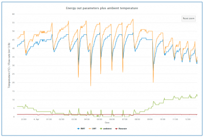
Let's say we have a 12kW (real output) heat pump, and a realistic minimum before it starts to cycle output of 25% ie 3kW. Given a relatively fixed flow rate of say 0.36 litres/sec (this is the usual Midea flow rate, give or take) and fluid specific heat of say 4.0 to allow for some antifreeze, that means we need a delta t of around 2.1 - but this is where it gets complicated. On a Midea unit, as I understand it, the only parameter we (or the unit itself) can control is the LWT. But somehow the delta t does get modulated (controlled). See how in this chart the delta t gets less as the ambient temp gets warmer:
Overnight, when it was colder, the delta t was 5 degrees or more (perhaps as high as 8 or 9), during the day, it drops to around 3 degrees, while the flow rate remains pretty constant.
As i understand it, the only things that affect the LWT/RWT delta t are the flow rate (faster = lower delta t, less time for heat to transfer) and rad/room delta t (warmer room = less heat loss from rads). But both of these parameters are relatively fixed. So what is controlling the delta t???
And why is the unit cycling? Note the overnight cycles are defrosts (LWT goes below RWT), it is the daytime cycles that represent true short cycling. The chart show it can reduce the delta t from 8 to 3 - why not reduce it to 2, which would correspond with about the unit's minimum output? Why not allow control of the flow rate? Why not let it reduce it's output to 10% of max output?
As I mentioned a short while ago, might not a volumiser help reduce cycling?
The more I look at this, the more confused I get.
Midea 14kW (for now...) ASHP heating both building and DHW
Posted by: @cathoderayare those COPs credible? I ask, because if they are not, then the underlying data is suspect.
This is the data coming directly out of the Samsung outdoor unit via modbus. So it is as accurate as the Samsung units. There may be some timing issues, but when averaged comes out to 5.7. [heating only]
My flow temp is 28 degC and the outside temperature is 10 degC so these are very likely correct and over a day cop is about 10% higher than samsung reports, probably because the samsung unit assumes glycol is being used, which I am not using.
]Posted by: @cathoderayBut both of these parameters are relatively fixed.
Well the rad room can be controlled, increase flow temperature you increase the ability to emit heat - to a point, the room temp will likely catch up
Posted by: @cathoderayAs I mentioned a short while ago, might not a volumiser help reduce cycling?
Once all my downstairs is converted to UFH, this issue should go away.
- 27 Forums
- 2,495 Topics
- 57.8 K Posts
- 453 Online
- 6,220 Members
Join Us!
Worth Watching
Latest Posts
-

Below is a better quality image. Does that contain all ...
By trebor12345 , 4 minutes ago
-
Sorry to bounce your thread. To put to bed some concern...
By L8Again , 6 minutes ago
-

@painter26 — they (the analogue gauges) are subtly diff...
By cathodeRay , 41 minutes ago
-

RE: What determines the SOC of a battery?
The answer from Fogstar was crisp. My hypothesis, su...
By Batpred , 1 hour ago
-

RE: Electricity price predictions
I am always impressed with how you keep abreast of so m...
By Batpred , 1 hour ago
-

RE: Setback savings - fact or fiction?
I fully understand your reasoning, same steady inputs s...
By cathodeRay , 1 hour ago
-
RE: Humidity, or lack thereof... is my heat pump making rooms drier?
@majordennisbloodnok I’m glad I posted this. There see...
By AndrewJ , 2 hours ago
-
RE: Testing new controls/monitoring for Midea Clone ASHP
@tasos and @cathoderay thanks. I have some history grap...
By benson , 4 hours ago
-
Our Experience installing a heat pump into a Grade 2 Listed stone house
First want to thank everybody who has contributed to th...
By Travellingwave , 4 hours ago
-

RE: Solis inverters S6-EH1P: pros and cons and battery options
Just to wrap this up here for future readers: The S...
By Batpred , 7 hours ago
-
RE: Struggling to get CoP above 3 with 6 kw Ecodan ASHP
Welcome to the forums.I assume that you're getting the ...
By Sheriff Fatman , 7 hours ago
-
RE: Say hello and introduce yourself
@editor @kev1964-irl This discussion might be best had ...
By GC61 , 9 hours ago
-

RE: Oversized 10.5kW Grant Aerona Heat Pump on Microbore Pipes and Undersized Rads
@uknick TBH if I were taking the floor up ...
By JamesPa , 23 hours ago
-

RE: Getting ready for export with a BESS
I would have not got it if it was that tight
By Batpred , 1 day ago
-
RE: Need help maximising COP of 3.5kW Valiant Aerotherm heat pump
@judith thanks Judith. Confirmation appreciated. The ...
By DavidB , 1 day ago
-

RE: Recommended home battery inverters + regulatory matters - help requested
That makes sense. I thought better to comment in this t...
By Batpred , 1 day ago
-
Bosch CS5800i 7kW replacing Greenstar Junior 28i
My heat pump journey began a couple of years ago when I...
By Slartibartfast , 1 day ago
-

RE: How to control DHW with Honeywell EvoHome on Trianco ActiveAir 5 kW ASHP
The last photo is defrost for sure (or cooling, but pre...
By JamesPa , 1 day ago
-

RE: Plug and play solar. Thoughts?
Essentially, this just needed legislation. In Germany t...
By Batpred , 1 day ago
-
RE: A Smarter Smart Controller from Homely?
@toodles Intentional opening of any warranty “can of wo...
By Papahuhu , 1 day ago
-
RE: Safety update; RCBOs supplying inverters or storage batteries
Thanks @transparent Thankyou for your advic...
By Bash , 1 day ago
-
RE: Air source heat pump roll call – what heat pump brand and model do you have?
Forum Handle: Odd_LionManufacturer: SamsungModel: Samsu...
By Odd_Lion , 1 day ago
-
RE: Configuring third party dongle for Ecodan local control
Well, it was mentioned before in the early pos...
By F1p , 2 days ago

