How To Deal With a Heat Pump Nightmare
@iantelescope You mentioned; ‘
Your photograph looks a wee bit like me ...........
ian’
Commiserations Sir! 😉
Regards, Toodles.
Toodles, he heats his home with cold draughts and cooks his food with magnets.
Hi Toodles
I have been contemplating my Heat Pump Fiasco ............
Perhaps Hans Christian Anderson sums it up perfectly........
The King is in the altogether, but altogether, the altogether He's altogether as naked as the day that he was born The King is in the altogether, but altogether, the altogether It's altogether the very least the King has ever worn".
For naked kings read Heat Pumps!
Having been told, by the NIC, that, following the third STRIKE_OFF of my "Installer"
"You are NOT Going to like this ............but Nothing can be Done!"
Were it Not for the intervention of my Member of the Scottish Parliament, I would have faced a total bill of £14000 following the Striking OFF of my "installer" by the NIC.
The HES in Scotland initially refused to repay the Grant and loan because of the performance of my "installer".
In the event, a "Drawdown Payment " was arranged to provide me with the Grant of ~£5000 , while still having to pay £42 per month for the £2500 Loan!
I spent another £3500 on replacing the Microbore Pipes and the replacing ALL of the radiators.
I spent a further £922.80 when Told that "I Must remove my Gas boiler .........it being "too difficult to install the necessary Valves etc".
ps. I look more than a wee bit like you Toodles!
@iantelescope As I said before regarding similarities of Fizoggs - Commiserations! Regards, Toodles.
Toodles, he heats his home with cold draughts and cooks his food with magnets.
The Control Philosophy for Heat Pumps
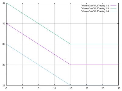
My Heat pump controls the Water Temperature by measuring the outdoor Temperature and using the Water -Law Graph :
The Y Coordinate of the Water Law Graph shows the required Water Temperature as the outdoor Temperature changes.
The Actual Water Temperature is found by adding an Offset Temperature using the Displayed Water -Law Thermostat:
With the required Water Temperature found by adding the Thermostat Offset to the Water Law Graph.
Here, the 1.2 C Offset produces a Water Temperature of 42.4 C.
Required Water temperature = Water-Law-Graph( Outdoor Temperature) + Offset.
The Actual Resulting Water Temperature is set by measuring the difference between the Required Water Temperature and the Resulting Water Temperature.
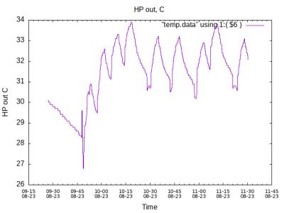
The Water Law Thermostat cannot maintain the Actual Water Temperature exactly at the Required Water Temperature , with the resulting water temperature shown in the following graph:
The Water Temperature is here oscillating , or Cycling , with a period of ~10 Minutes.
When the Water Law Thermostat detects the Water Temperature falling below the Required Temperature a Power Demand is issued to the Heat Pump.
With Power heating the water , the Water Temperature sharply increases until stopped by the cycle Running Time.
The Water Temperature then fall exponentially with a time constant determined by the Volume ( Mass) of Water within the Water Pipes.
The Cycle is stopped when the Water Temperature again falls below the required Temperature.
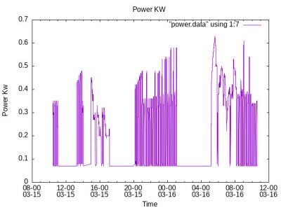
If the Cycle time is Less than 15.. 20 minutes , and the Cycling is seen to run continuously the Heat Pump is considered to be "Short Cycling".*
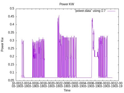
A particularly violent example of "Short Cycling" on 15th / 16 th March 2024
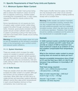
Both the MCS and Samsung have issued Warnings about Short Cycling:
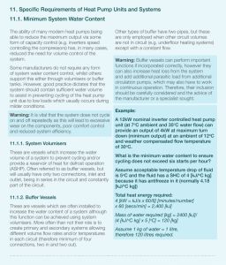
A MCS Warning
Notice here the emphasis on the Minimum Power that the Heat Pump inverter can supply, here, ~2.5 kw.
The Minimum Inverter power is every bit as important as the Maximum power!
Most manufacturers Do NOT publicise their Minimum Inverter Power, presumably because they have something to hide!
A Warning for Samsung users.
* See the DECC Reports on a 15/20 minute Lower limit for cycling time and an advised 6 minute lower limit for Running Time.
ian
p.s I hope I have not insulted you by not "teaching your granny to suck eggs".
I Hope my Technical writing style does NOT offend!
Posted by: @iantelescopep.s I hope I have not insulted you by not "teaching your granny to suck eggs".
I Hope my Technical writing style does NOT offend!
No and no.
Thanks for posting.
105 m2 bungalow in South East England
Mitsubishi Ecodan 8.5 kW air source heat pump
18 x 360W solar panels
1 x 6 kW GroWatt battery and SPH5000 inverter
1 x Myenergi Zappi
1 x VW ID3
Raised beds for home-grown veg and chickens for eggs
"Semper in excretia; sumus solum profundum variat"
To Buffer Or Not To Buffer , that is the Question?
Spring 2024.....
With Spring my Heat Pump resumes "Short Cycling" as shown in the following graph:
What Causes Short Cycling?
With Heat Pump Power Controlled by an "Inverter" my Heat Pump reverts to Cycling below the Inverter Minimum Power, in my case ~2.5 kw.
Cycling Time is set by the time taken to Heat the volume of water in the water pipes in response to the Heat Pump inverter Minimum power.
Energy Equations at Inverter Minimum Power
The total Input Energy when operating at Minimum power is
Input_Energy = Minimum_Power X Run_Time .................................................................................................................................................................(1)
Where Run_Time is measured in seconds.
The Total Power consumed in heating the Volume of water contained in the buffer and the pipes
Energy Consumed = Specific_Heat_of_Water X Mass_of_Water_within Water_pipes X Maximum_Allowable_Temperature _Drop_Across_Buffer .........(2)
The Input_Energy must equal the Energy_Consumed , i.e. ................1 = 2
For my Heat Pump :
Minimum power = 2.5 Kw
Buffer Volume = 50 Litres.
Volume of Pipes = 6 Litres.
Maximum_Allowable_Drop_Across_Buffer = 5 C.
Therefore, for my Heat Pump:
2.5 X Rum_Time = 4.18 X 56 X 5
Therefore , the Run Time in minutes for My Heat Pump would be Run_Time = 4.18 X 56 X 5 / (2.5 X 60)
giving a Run_time of ..............................7.8 minutes:
Trade Off between "Short Cycling " and Efficiency......
The Calculation above depends upon the Value of the "Minimum_Allowable_Temperature_Drop , here assumed to be 5C.
My Heat Pump Already has a Temperature Drop of ~5 +/- 2 C Across a Heat Exchanger.
With a further worst case Piping Temperature Drop of ~ 8 +/- 2 C the total Temperature Drop is Already ~14C .
At a these Water Temperatures , the Radiators are Already operating at an efficiency of X 0.63 When operating at the Specified Working Water Temperature.!
The Compromise !
Given that I cannot afford any further Temperature Drops across the Transmission network A Buffer was fitted in Parallel.
The Parallel Buffer Tank was originally installed to overcome the De-icing Problem.
The Parallel Buffer Tank has been successful in stopping the de-icing problem but NOT the "Short Cycling".
Given that the NIC says that "You are NOT Going to like this ...............but that , given the application of extensive sanctions against your "installer" ,
NOTHING CAN BE DONE".
Hypothermia or Bankruptcy ?
ian
PS Please check my calculations against those given in the MCS Data Sheet .
pps Please forgive my "simplistic Technical authorship"
Installing a "Serial" or "Parallel" Buffer to reduce "Short Cycling" ?
Following a visit from a French Samsung Engineer I had a friendly dispute about fitting a buffer in Series with the Input port of my Heat Exchanger
OR
installing the buffer in Parallel , i.e. across the ports of my Heat Exchanger.
The Frenchman was amused by my description of the "in Series" or "in Parallel" electrical speak!
The Parallel Buffer Across the Heat Exchanger Ports
My Heat has , currently, a buffer fitted between the ports of my Heat Exchanger.
When operating above the Minimum Inverter power of ~2.5 Kw the Heat Pump Power is controlled by the Inverter.
When operating below the Minimum Inverter power , the Heat Pump reverts to Cycling power control.
When cycling, the Power from the Heat pump is used to heat a volume of Water , here, when operating "in Parallel", equalling the Buffer Volume plus the volume of the Heat Exchanger.
The Heat Exchanger volume is unknown but is thought to be insignificant compared to that of the Buffer Tank.
When operating at Minimum Power the Energy input to heating the Water in the Buffer Tank is:
Input Energy Required to heat Buffer tank = Minimum_power X Run_Time ( Seconds) ...........................................(1)
The Input Energy is used to heat the Buffer tank:
Energy consumed in heating water = Specific_Heat_of_Water X Buffer_tank_Volume X Temperature_Difference _Across_Heat_Exchanger_ports...........(2)
where the Temperature_Difference _Across_Heat_Exchanger_ports is found by a pair of 18B20 Sensors, found to be ~4 C.
On equating 1) and 2) :
2.5 X Run_Time = 4.18 X 50 X 4
Therefore:
Run_Time ( Minutes) = 4.18 X 50 X 4/(2.5 X 60) = 5.57 Minutes.
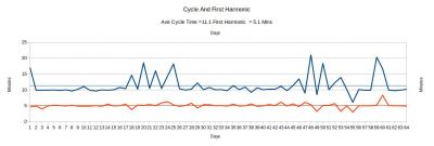
The Actual Run_Time measured is shown in the Graph:
With a Measured Average Run_Time of 5.16 Minutes.
The Run_time Calculated for the case of the "in Series" Buffer Tank was 7.8 minutes.
Conclusions
The fitting of a buffer Across the ports of my Heat Exchanger make little difference to that of fitting the Buffer "in Series" with One of my Heat Exchanger ports!
When the buffer tank is fitted Across the Heat Exchanger ports ,"Short Cycling" is a function of the Heat Pump Minimum Inverter Power , the Temperature Drop Across the Heat Exchanger Ports and the Buffer Tank Volume.
In Parallel , the Buffer acts as a shorting load across the Heat Exchanger ports, although, I have not, as yet, measured the resulting losses.
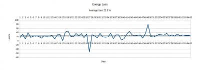
In parallel , the losses are shown on the following graph:
With an average loss of 24.8 % including the Heat Exchanger , Parallel Buffer and piping.
When the buffer tank is fitted in line with only one Heat Exchanger Port , i.e. "In series operation ","Short Cycling" is a function of the Heat Pump Minimum Inverter Power , the Temperature Drop Across the Buffer tank and the Buffer Tank Volume.
When the buffer tank is fitted in line with only one Heat Exchanger Port , i.e. "In series operation", the Operating Water Temperature as displayed on the Heat Pump front panel , will be significantly reduced . The Radiators will emit significantly reduced power.
@Mars
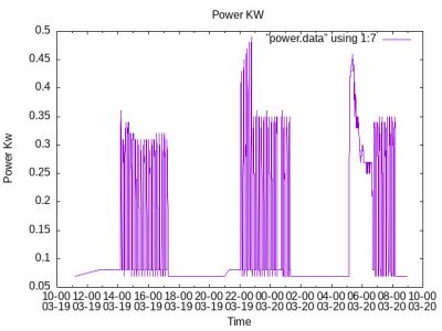
The Costs of "Short Cycling".
My Heat Pump is "Short Cycling" as shown in the graph
This "Short Cycling " results in motor wear & water contamination :
Water contamination is covered by the BS7593 Directive : Issued in 2019 to replace Similar EEC Directives.
The Following is an edited version of the BS7593 :2019 instructions provided by Fernox .
Published in May 2019 the new BS 7593:2019 provides clear guidance on the preparation, commissioning and maintenance of domestic central heating and cooling water systems.
1.Clean
Before an existing central heating system is dosed with chemical water treatment or a filter is installed, it is vital that it is cleaned to remove any existing sludge or debris build-up. For best results, installers should use a recognised cleaning method such as power flushing, mains pressure or gravity cleaning.
It is also important that systems are cleaned before the boiler is installed or when a new boiler has been isolated from the rest of the system. This will prevent any existing sludge or debris within the system reaching and depositing in the boiler and causing lasting damage.
2. Guard
Once a central heating system is cleaned, it is key to make sure that sludge and debris does not build-up once more. The new BS 7593:2019 code of practice states that, in order to do this, an in-line filter should be permanently installed to provide continued protection and maintain system efficiency.
It is important that the chosen filter can effectively capture and contain both magnetic and non-magnetic debris to keep the system as clean as possible. Filters manufactured by leading water treatment specialists, that utilise a powerful neodymium magnet and other technology such as Hydronic Particle Separation (HPS) are better able to achieve this – and can therefore deliver optimum results.
For ease of install, it is important to consider whether the filter can be installed in a variety of orientations, such as horizontal, vertical, or with the capability of being installed up to 45° orientation in order to fit small confined spaces.
3. Protect
To protect a central heating system from corrosion, scale, microbial fouling for low temperature heating systems, installers should dose the system with the correct quantity of chemical water treatment products. This should include Protectors to protect against harmful sludge and debris build-up. It is best to choose products from a reputable manufacturer, to guarantee that the chemicals will continue to protect the system effectively.
It is also important that systems are dosed correctly – the Fernox ‘F’ range of chemicals, for example, have recently been re-formulated to include more active ingredients; and can now treat systems up to 130 litres, 16 radiators, or underfloor systems up to 250m2. This will significantly lower the chance of under dosing, to cover 97% of UK homes.
For low temperature or underfloor heating circuits, which are at risk from bacterial contamination and fungus, specialist biocides are available. Fernox Biocide F7, for example, protects against bacterial slimes, algae and biofilms forming, which can cause blockages, inefficiencies and ultimately breakdowns.
System Filters can directly protect the boiler to ensure that any circulating debris that is present within the system does not reach vulnerable components such as pumps or heat exchangers.
For hard water areas with a ppm of 200 and above, a scale reducer should be fitted to mitigate the effects of limescale. Electrolytic Scale Reducers offer whole house protection whilst Magnetic Scale reducers are designed to be fitted next to the boiler for single appliance protection.
4. Maintain
BS 7593:2019 states that servicing of in-line filters is recommended as part of the re-commissioning process, ideally as part of the annual boiler service and according to the manufacturer’s instructions – to remove any sludge or debris that has been captured. This will ensure that the filter continues to work at its best, removing contaminants from the system.
5.Test
To ensure full system protection, inhibitor levels should be checked throughout its life cycle. This can be achieved with a full laboratory analysis of the system water. Simple test kits are available – these require a sample of the water to be taken and sent off to a laboratory for testing.
In order to meet the requirements of BS 7593:2019, it is vital that installers look to specialist manufacturers who demonstrate an understanding of the on-site challenges, with an extensive product portfolio that offers a solution for every application – and ensures compliance on every project.
ian
Example of a customer and a bankrupt installer
Interesting which organisation covered it under their "promise"
Not sure if it has been posted on the forum before, it may be in another thread somewhere.
@jeff interesting to see Grant’s ‘involvement’ in this. On Sunday we have a podcast episode that addresses a lot of the shortcomings highlighted in this piece from a manufacturer support and warranty perspective.
Buy Bodge Buster – Homeowner Air Source Heat Pump Installation Guide: https://amzn.to/3NVndlU
From Zero to Heat Pump Hero: https://amzn.to/4bWkPFb
Subscribe and follow our Homeowners’ Q&A heat pump podcast
Posted by: @editor@jeff interesting to see Grant’s ‘involvement’ in this. On Sunday we have a podcast episode that addresses a lot of the shortcomings highlighted in this piece from a manufacturer support and warranty perspective.
Obviously we don't know all the detail.
I do find it interesting from a public relations exercise.
Am surprised at the lack of response from Grant. On this basis alone i doubt i would use them in our next home. They have really shot themselves in the foot here but not engaging with a newspaper.
It would have been easy cheap PR to get involved in my humble opinion given the press coverage in a newspaper. The average Guardian reader may well be a good target market for heat pumps.
It is interesting how much official accreditation the installer had directly rather than subcontracting work. I wonder how common that is. It certainly helped for this customer.
Good on a journalist who clearly wasn't an expert in heat pumps picking this up. In fact that may actually have helped as they tried lots of ways to sort it out and were not caught up with group think and any previous conceptions on responsibility. The "computer says no" attitude of some organisations can be frustrating in my personal experience.
In think... To speed up the uptake of heat pumps the sector as a whole needs to fix customer issues quickly. It is in their mutual interest. Else a few small stories will get in the way of the good work going on and the case for heat pumps.
While the article ends on a positive note with promises to handle repairs, forum experiences here suggest there’s often a long way to go after that point. Even once they commit to repairs, plenty of issues can still surface. Unfortunately, the involvement of NICEIC isn’t always reassuring either, as they’ve earned a reputation for inconsistent follow-through on cases like this.
And you’re spot about Grant @jeff. Missed opportunity. I follow all the major heat pump manufactures on social media, and Grant’s feeds on LinkedIn are dominated by corporate hospitality and team building at Bath Rugby matches.
Buy Bodge Buster – Homeowner Air Source Heat Pump Installation Guide: https://amzn.to/3NVndlU
From Zero to Heat Pump Hero: https://amzn.to/4bWkPFb
Subscribe and follow our Homeowners’ Q&A heat pump podcast
- 22 Forums
- 2,089 Topics
- 45.9 K Posts
- 48 Online
- 3,375 Members
Join Us!
Trusted Installers
Struggling to find a reliable heat pump installer? A poor installation can lead to inefficiencies and high running costs. We now connect homeowners with top-rated installers who deliver quality work and excellent service.
✅ Verified, trusted & experienced installers
✅ Nationwide coverage expanding
✅ Special offers available
Latest Posts
-
RE: My misgivings about installing ASHP and solar panels via the ECO4 scheme...
@grantmethestrength "...have a morning pow wow over a n...
By Dwynwen , 13 minutes ago
-
RE: RDSAP10 effect on existing heat pump EPC rating?
@aaron There's the rub, the database does not list my ...
By AF1 , 1 hour ago
-
RE: Renewable Heating Hub Homeowners' Q&A Podcast
@editor excellent news, congratulations and well deserv...
By ASHP-BOBBA , 3 hours ago
-
RE: Getting the best out of a heat pump - is Homely a possible answer?
@majordennisbloodnok Thanks for above. I have given it ...
By benson , 3 hours ago
-

RE: Who's your electricity provider and what's your tariff?
I’d be interested to know if anyone uses the NetZero ap...
By Toodles , 5 hours ago
-
RE: Vaillant AroTherm Plus 7kW
Depends on the flow temperature; the Czech data sheet i...
By JamesPa , 9 hours ago
-
RE: Renewables & Heat Pumps in the News
Thanks @lucia I look forward to some technical facts as...
By Judith , 9 hours ago
-
RE: Commencing on an ASHP Installation Process
Yes, it's "doable" if everything goes to plan, they arr...
By Old_Scientist , 1 day ago
-
RE: How not to install a heat pump
You are right. Thinking on this has evolved over the p...
By JamesPa , 2 days ago
-

@ashp-bobba ‘Wattson, how many grammes of Co2 are you r...
By Toodles , 2 days ago
-
RE: DHW SET UP with Samsung gen 5
Thats good news indeed, you are very likely almost ther...
By JamesPa , 2 days ago
-
RE: Plate heat exchanger considerations
As far as I can tell my vented system would have a peak...
By Scalextrix , 2 days ago
-
RE: Air Changes per Hour - ACH and the MCS requirement
There have been a few discussions dotted around (e.g. I...
By Declan90 , 2 days ago
-

RE: Heat Pump Servicing & Maintenance – Good Value or Rip-Off?
Having made some enquiries locally I have found a compa...
By Morgan , 2 days ago
-
RE: I don't need any heating in the summer. How do I turn my Samsung heat pump off?
Thats great Someone else is struggling with this in a...
By JamesPa , 3 days ago
-
@bart Best of luck moving forward, I look forward to he...
By ASHP-BOBBA , 4 days ago


