I'm unsure of the sources from which you derived your initial list, but I'm pleased to see it being altered as others contribute to this topic.
Low-voltage/battery cable-sizing is most commonly calculated by manufacturers by using American Wire Gauge sizes (rather than the mm² which we use this side of the pond).
From their tables you need to select the size which carries the maximum continuous current you expect to have.
The industry which has most experience of this is probably the marine sector.
They de-rate current capacities according to conditions such as
- passing a wire through a conduit
- cable length (voltage drop)
- ambient temperature
- the material to which a wire is clipped
- the proximity of other wires which may get hot
The last one suggests that twin-cables should be avoided!
I wonder if @chickenbig would like to comment?
Amongst the reputable suppliers in the UK, have a look at 12-volt Planet.
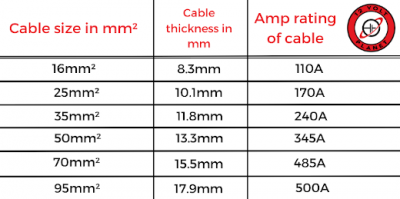
They have wide-ranging advice on their website, https://www.12voltplanet.co.uk/news/cable-sizes. There you'll find a wire size/current chart of which I'm reproducing this snippet:
The rule-of-thumb is that you shouldn't be drawing current (discharging) from a battery at a current greater than the Ah capacity of that battery.
That charge/discharge rate is called C
If you're building a battery with 280Ah cells, then the maximum continuous current you'll want to draw from it is 280A
Thus if you're starting point is a Mason box with 305Ah cells, you're not going to need a more hefty cable than 50mm²
But you then state that you'll be adding a 150A in-line fuse for each battery...
... thus suggesting a 25mm² wire would be adequate.
The 35mm² wire you're now contemplating is plenty big enough, and will exhibit very little voltage drop.
But cost might also be a considerisation.
Fuses for each battery are certainly highly recommended...
... but shouldn't be the method used to manually isolate a battery of course!
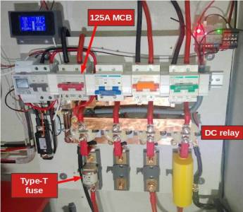
That's the job of a DC-rated relay or trip.
The fuse isn't there to 'protect the battery' either.
If you attempt to draw 4000A from an LiFePO4 battery, then it will happily oblige you!
That's the nature of its chemistry.
The fuse(s) need to blow fast if a connected device fails.
In the event of a component failure in your inverter causing a near-short-circuit, the fuses shut off the energy supply and prevent a fire.
For that reason I recommend (and use) Type-T fuses.
The Type-T is housed in a ceramic body with BS88-standard lugs at each end to accept a bolt.
The fuse body is filled with a chemical powder which ensures complete vaporisation of the internal 'wire', rather than it merely melting at a hot-spot.
It needs to break the circuit instantly, rather than create an arc within the fuse.
You will note that I've made a fair amount of this battery-combiner board rather than buying in ready-made parts.
Sometimes what you really want isn't available.
My four batteries and inverters connect together using very solid copper bus-bars.
Compare that to the plastic-covered terminal blocks you'll see on the photo posted above by @chickenbig
Neither approach is necessarily 'right' or 'wrong'.
I'm posting my photo so that others can better evaluate the options.
We both agree on the need to have non-combustible boards.
Chickenbig mentioned Magnesium Oxide board...
and I've used https://www.fermacell.co.uk/en on which to mount the fuse-holders, DIN-rails and busbars.
Save energy... recycle electrons!
a quick note re the yellow comms cable, it works fine with my seplos 280L and sunsynk 5.5 ecco - just set battery type to lithium and plug it into the can bus on the inverter and the can port on the seplos - works fine !!
Re- 280L Seplos vertical kit - I sent photos and a description to Fogstar, about the lack of compression and non-flat base as the kit parts I had, asking if a part was missing. They replied that other customers had asked similarly, but no - I had all the parts! Others had used plywood on the base to flatten it. A bit shoddy by Seplos - unless I am very confused- it really needs an extra piece in the base. Anyway, the MgO I used will be fine for the task I think.
Posted by: @roblthe 3.6kW sunsynk hasn't got an external fan, so tends to get pretty hot [...]. I've glued on 3 low power fans to it, and a 40C bimetallic thermal switch [...] The fans will be below the heatsink, blowing upwards.
That will probably work fine, but is noisy and doesn't offer the optimal strategy.
The output side of a fan has turbulent air.
It's 'out of control' and will pass across the heatsink surfaces in a haphazard way.
Some of the aluminium fins will have air rushing by so fast as to absorb little heat...
... whilst there will be other pockets of air which remain circulating in a vortex, and not taking the heat away.
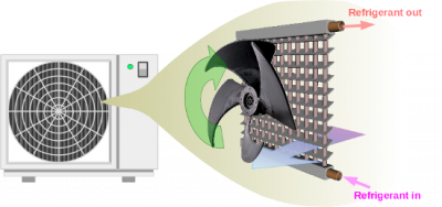
Cooling fans are best used in a pull orientation, whereby a steady stream of air passed through the fins towards the fan.
I used to have an 8kW (commercial) battery storage unit here on a national trial.
It had three fans at the bottom, trying to force air upwards through the electronics of the inverter.
The manufacturer had realised that something wasn't right, and had mounted the (3rd-party) inverter upside down within the outer casing,
... an 'inverted inverter'!
What they should've done was to open up the inverter itself and turned the fans over.
Then it wouldn't have made so much noise either!
Have a look at air-source heat-pumps.
They use large fans to pull air through the fins of a heat-exchanger.
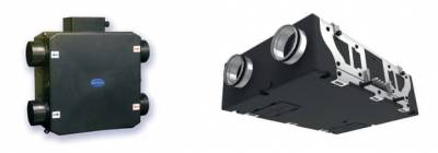
The same is true for the two fans in a whole-house Mechanical Ventilation with Heat Recovery (MVHR) unit,
which is why you must connect the air-ducts to the correct ports:
Save energy... recycle electrons!
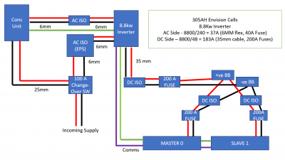
Ok so I think I have my design based on all of your feedback. Remaining question is will 6mm cable on the AC side be sufficient. Due to increased cost (additional fuses etc) i will opt for just 2x batteries initially, but keep the option of adding a third in the future.
Feedback much appreciated. Note I plan to utilise the EPS function with a manual changeover switch.
Posted by: @transparentThe last one suggests that twin-cables should be avoided!
I wonder if @chickenbig would like to comment?
states that 35mm2 twinflex is able to carry 158A (at 60 degrees C), which was sufficient for the installation I made, but perhaps not suitable for the original poster who wants 190A. To be fair, the twinflex cables provided double insulation, and their profile is two cables next to each other which is what one might expect were the cables placed in ducting for mechanical protection. This is why I feel a 5kW inverter is a particular sweet-spot (thinner cables, cheaper fuses).
@chickenbig So for my install I will indeed need 50mm cables DC side (8800w/48v = 183.3A). Although 35mm surface clipped is good to 203Amps?
Posted by: @makia2023for my install I will indeed need 50mm cables DC side
You might need to turn to 35mm2 welding cable (e.g. https://hilltop-products.co.uk/pvc-battery-welding-cable-35mm-455-0-30mm-conductor-240-amps.html) which, rated to a higher temperature, handles up to 240A continuous. Being single insulated you do need to think about some trunking to protect them from mechanical damage (although part of me thinks that industrial use for welding is a harder life than sitting on a wall).
I forgot to mention that you may also want to use (adhesive lined) heatshrink to cover the crimps. You will have plenty of crimps to cover (36 in total). I used https://cableties.co.uk/products/3-1-black-adhesive-lined-dual-wall-heatshrink-tubing-mini-reel-4m-roll for the 35mm2 cable.
Posted by: @makia2023How does my diagram look? About right? Anything you might change?
The DC side of the wiring looks good to me (although transparent and myself differ over whether a combined fuse/isolator is less acceptable than an isolator and bolted down fuses).
On the AC side I see the green wire (earth, I presume) ends in the consumer unit. Search anti-islanding on this forum for details, but basically you can not rely on the DNO's earth if you want the inverter to provide power in case of a power-cut. You also need an RCD and MCB for the inverter, and may also want a surge protection device (the inverter being expensive). Also you do need to consider the location of the CT clamp.
Posted by: @makia2023So for my install I will indeed need 50mm cables DC side (8800w/48v = 183.3A).
Can I refer back to your first post in this topic?
You stated your strategy was to use three battery packs.
The only cables which have to carry a possible 183A are those which run from the inverter to the first battery in a chain.
But you should have a DC-rated double-pole isolator between inverter and batteries;
That isolator needs to carry more than 125A, and therefore cannot be a commonly-available MCB mounted on a DIN-rail.
It must be an MCCB (Moulded Case Circuit Breaker) from a reliable supplier and capable of taking 200A or more. (It's a safety device!)
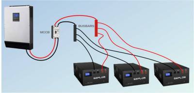
At those currents, my preference would be to link all three batteries to a pair of busbars, using smaller wires, but of equal length.
That means you only use the 35mm² or 50mm² wire either side of the MCCB, mounted close to the inverter.
Others may disagree, and suggest you interconnect the three Seplos enclosures in parallel, using the leads which came with them.
But that's the point of having a discussion forum here. 🙂
Fuses. Your diagram shows individual fuses for each battery pack, and an overall fuse.
You wouldn't use both.
You need to decide whether each battery enclosure should have a fuse, or just one for the entire DC side of the inverter.
Think what type of fault would cause a fuse to blow.
And then think what would be the effect of such a fuse having blown.
In your present circumstances it won't make a huge difference because you've only got one inverter.
But what if that inverter had the ability to work in parallel with another which you wanted to add later?
Save energy... recycle electrons!
Posted by: @makia2023will 6mm cable on the AC side be sufficient.
That part of the installation should be undertaken by a qualified electrician.
So the cable size is their decision.
They use look-up tables when deciding which wire size is required.
A 6mm² twin-and-earth cable is rated 53A in free air.
If it's clipped direct to a wall or board, then it's de-rated to 47A.
And if you run it within a conduit buried in a wall, then it's only 32A.
Even those figures are subject to additional factors.
There are considerations of cable-length and the ambient temperature of the area through which it passes.
That's why these guys are qualified and allowed to issue certificates for the installation.
There's more to this than might first appear.
In your case an inverter rated at 8.8kW should draw no more than 36A
and it's therefore most likely than your electrician will opt for 6mm² cable.
But he will make that decision based on the point in the run where the cable is least able to shed heat.
Save energy... recycle electrons!
- 27 Forums
- 2,495 Topics
- 57.8 K Posts
- 477 Online
- 6,220 Members
Join Us!
Worth Watching
Latest Posts
-
RE: Testing new controls/monitoring for Midea Clone ASHP
Here’s a current graph showing a bit more info. The set...
By benson , 51 seconds ago
-
RE: Setback savings - fact or fiction?
True there is a variation but importantly it's understa...
By RobS , 1 minute ago
-

Below is a better quality image. Does that contain all ...
By trebor12345 , 28 minutes ago
-
Sorry to bounce your thread. To put to bed some concern...
By L8Again , 30 minutes ago
-

@painter26 — they (the analogue gauges) are subtly diff...
By cathodeRay , 1 hour ago
-

RE: What determines the SOC of a battery?
The answer from Fogstar was crisp. My hypothesis, su...
By Batpred , 1 hour ago
-

RE: Electricity price predictions
I am always impressed with how you keep abreast of so m...
By Batpred , 2 hours ago
-
RE: Humidity, or lack thereof... is my heat pump making rooms drier?
@majordennisbloodnok I’m glad I posted this. There see...
By AndrewJ , 2 hours ago
-
Our Experience installing a heat pump into a Grade 2 Listed stone house
First want to thank everybody who has contributed to th...
By Travellingwave , 5 hours ago
-

RE: Solis inverters S6-EH1P: pros and cons and battery options
Just to wrap this up here for future readers: The S...
By Batpred , 8 hours ago
-
RE: Struggling to get CoP above 3 with 6 kw Ecodan ASHP
Welcome to the forums.I assume that you're getting the ...
By Sheriff Fatman , 8 hours ago
-
RE: Say hello and introduce yourself
@editor @kev1964-irl This discussion might be best had ...
By GC61 , 9 hours ago
-

RE: Oversized 10.5kW Grant Aerona Heat Pump on Microbore Pipes and Undersized Rads
@uknick TBH if I were taking the floor up ...
By JamesPa , 24 hours ago
-

RE: Getting ready for export with a BESS
I would have not got it if it was that tight
By Batpred , 1 day ago
-
RE: Need help maximising COP of 3.5kW Valiant Aerotherm heat pump
@judith thanks Judith. Confirmation appreciated. The ...
By DavidB , 1 day ago
-

RE: Recommended home battery inverters + regulatory matters - help requested
That makes sense. I thought better to comment in this t...
By Batpred , 1 day ago
-
Bosch CS5800i 7kW replacing Greenstar Junior 28i
My heat pump journey began a couple of years ago when I...
By Slartibartfast , 1 day ago
-

RE: How to control DHW with Honeywell EvoHome on Trianco ActiveAir 5 kW ASHP
The last photo is defrost for sure (or cooling, but pre...
By JamesPa , 1 day ago
-

RE: Plug and play solar. Thoughts?
Essentially, this just needed legislation. In Germany t...
By Batpred , 1 day ago
-
RE: A Smarter Smart Controller from Homely?
@toodles Intentional opening of any warranty “can of wo...
By Papahuhu , 1 day ago
-
RE: Safety update; RCBOs supplying inverters or storage batteries
Thanks @transparent Thankyou for your advic...
By Bash , 1 day ago
-
RE: Air source heat pump roll call – what heat pump brand and model do you have?
Forum Handle: Odd_LionManufacturer: SamsungModel: Samsu...
By Odd_Lion , 1 day ago
-
RE: Configuring third party dongle for Ecodan local control
Well, it was mentioned before in the early pos...
By F1p , 2 days ago

