There will still be a substation number plate on that pole.
Every pole on the grid is numbered, even if it has no transformer and no wires currently 'live' !
Save energy... recycle electrons!
@transparent the only number I can see is RSFCCA1
Our experiences with solar pv, ASHP, battery, and EV: ourhomeelectric.co.uk
Ah yes - I can see it:
Rear of Steevjo's Field - Code? - Couldn't Arrange 1 😉
So what's the number on the next pole?
Save energy... recycle electrons!
@transparent RSF CC13 is next
Our experiences with solar pv, ASHP, battery, and EV: ourhomeelectric.co.uk
I've run those pole numbers (and variations thereof) through NGEDs entire database of substations and that pattern of naming doesn't occur @steevjo
So I've emailed a senior NGED engineering manager to ask for assistance.
It's possible that the asset-number labels for those poles and transformer haven't been applied for some reason.
The labels you're seeing could just as easily refer to something else.
For example, CCA (Copper Covered Aluminium) is a type of cable commonly used for overhead wires in rural locations.
Save energy... recycle electrons!
Just a bit more re powerwall earthing…
The powerwall gateway includes a breaker to disconnect house live and neutral from incoming when there is a power outage - as required by regs.
it also includes a normally open breaker which closes during a power outage to restore the earth neutral bonding which has gone because the neutral has disconnected…
only the earth wire it connects to goes straight to the incoming PEN cable a few feet away - so can’t really see how neutral is still disconnected.
you can see all this in the diagram posted earlier.
NGED had this diagram (actually a similar diagram that better represents our house but with the same earthing arrangements) as part of the G99 application which was approved.
I admit I’m completely confused.
Our experiences with solar pv, ASHP, battery, and EV: ourhomeelectric.co.uk
@steevjo indeed. there are some photos of mine in that speakev thread, that I was able to take at one time when the sparks were here, showing the earths, they're all commoned - house, batteries, earth rod, DNO cable
My octopus signup link https://share.octopus.energy/ebony-deer-230
210m2 house, Samsung 16kw Gen6 ASHP Self installed: Single circulation loop , PWM modulating pump.
My public ASHP stats: https://heatpumpmonitor.org/system/view?id=45
11.9kWp of PV
41kWh of Battery storage (3x Powerwall 2)
2x BEVs
Let me provide the background detail which shows the electricity supply used for the majority of the UK population.
Protective Multiple Earth (PME) derives from the way in which local substation transformers are designed.
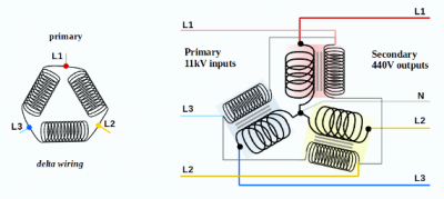
The 11kV 3-phase supply connects to the three primary coils of the transformer in a Delta pattern.
The Secondary windings are in a Wye pattern.
This not only provides the optimal efficiency for energy transfer using magnetic flux, but the centre-tap becomes the Neutral for houses which are connected to single-phase feeds.
That Neutral is connected to earth (ground) at the transformer.
It can therefore be used to provide an 'earth' to the houses.
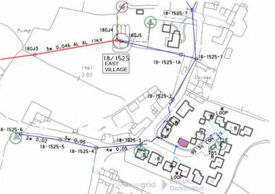
In practice it looks more like this...
... where there is local substation called East Village.
This map has been 'anonymised'.
East Village doesn't actually exist, nor is there a location with precisely this layout for the electricity supply.
The 11kV supply to the substation is marked in red.
It has one 440v Feed (blue) which divides into two.
The safety earth for the metal transformer itself isn't directly beneath it, but instead about 40m north.
I've circled that in light red.
The 440v 3-phase feed also has four points at which it is tied to earth.
Those are circled in green.
One of those points, closest to the transformer, is the one that creates the zero-volts reference for the Neutral.
The three other earth points are decided by the DNO according to local circumstances.
They are what makes this Feed a Protective Multiple Earth.
Each pole will have a label "PME", together with the pole number, such as 18/1525-1
If the house I've coloured in purple has a heat pump, EV charge-point or solar panels installed, there may be a regulation which requires the equipment to have its own earth stake.
But that local earth isn't the same as the earth provided by the DNO, which is derived from the Neutral feed.
Installers may not just add further earth points to the DNO's local supply.
Save energy... recycle electrons!
Thanks for the background @Transparent
Posted by: @transparentInstallers may not just add further earth points to the DNO's local supply.
But they clearly do.
To be honest I can see little difference between an earth spike and earth bonding to an incoming conductor. I know the purpose is different but both are wiring a piece of metal coming out of the ground to the DNO provided earth.
I absolutely understand that I don't understand enough of the details/know the rules. One option is I just trust the installers/NGED approval process and forget about it...
... but it's hard when what is there right now makes no sense to me.
Our experiences with solar pv, ASHP, battery, and EV: ourhomeelectric.co.uk
I may not appear to be responding directly to what you post @steevjo
but I am reading every point you've written to ensure that I cover it within my ongoing explanations. 🙂
EV charge points aren't installed by any electrician.
The firms that undertake this work have additional training and certification.
There are a number of safety components and practices which they must ensure are being incorporated.
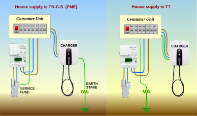
The main methods of installing an EV charger are these:
Notice the change in earthing arrangement, depending on whether the house earth is provided by the DNO (PME) or by using a ground-stake.
In each case the charger is earthed, and the householder can see a physical copper rod inserted into the ground at their house.
This makes it tricky for less-technical people to know whether it has been done correctly.
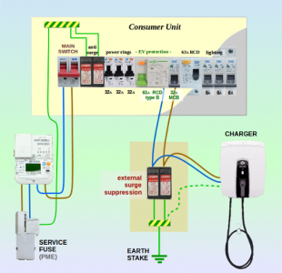
I'm now going to 'zoom in' on the PME version, on the left of the above diagram:
This more detailed view shows anti-lightning surge suppression for the EV charger.
It's separate from whatever surge suppressors may or may not be already installed in the house.
The new pair of suppression devices prevent the 'ground wave' created by a nearby lightning strike from entering the house.
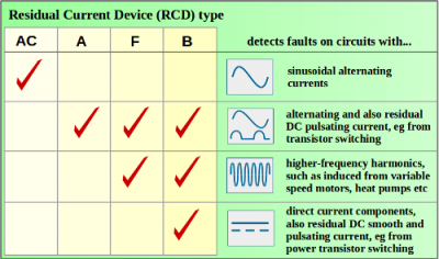
The second detail to notice is an RCD Type B in the consumer unit, next to the trip (MCB) which supplies the EV charger.
Type-B Residual Current Devices are the highest level of safety protection.
It's a double-pole device, costing about £250
It will interrupt the supply in case of fault currents occurring
- on the AC sine wave of the mains supply
- on any DC component which is induced by the charger
- on any high-frequency signal imposed on the mains supply by the charger
- on any pulsed or intermittent current imbalance
Some EV installers fit Type-A RCD units, which are a lot cheaper and easy to source.
This chart explains the four categories of 'earth leakage' protection:
So why is the earthing arrangement different for properties served by a PME supply?
This has to do with the possibility of damage to the (underground) feed from the substation which results in the Neutral being cut.
Remember that a house with PME has the earth provided by the wire being linked to Neutral at the 100A Service Fuse.
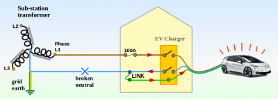
If the EV charger is incorrectly installed and uses the household earth, then it would look like this:
The EV charger still passes the LIVE to the car.
The return current passes back through the blue/neutral wire to the charger and on to the consumer unit, but can't return to the substation transformer through the DNO's underground cable.
Instead, it crosses the link to the earth wire and goes back to the car.
That causes the external metalwork of the car to rise to the same voltage as the LIVE. 😮
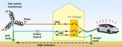
Even if the EV charger were also to have its own earth stake (which it shouldn't), that doesn't solve the problem:
The return current will indeed now find a path back to the transformer through the ground, but there is a high resistance via that route.
Consequently the metalwork of the car tends to 'float' at around 50-120v.
That's still enough to kill you.
When considering the earthing arrangement you have had installed, it is insufficient to consider that "it works, so it must be OK".
The whole point of a safety mechanism is to assess "how does it operate when there is a dangerous fault?"
Save energy... recycle electrons!
@transparent Thanks for the detailed explanation.
I looked into EV chargepoint earthing a couple of years ago when ours was installed. At the time there was a bit of debate about 'unicorn' devices that would enable a charger to detect neutral and earth problems so they could safely be installed in PME systems using the house earth without needing their own earth spike.
Our pod point has such a system - there's a decent write up here: https://pod-point.com/electric-car-news/earth-rod-details Interestingly (I'm sad) when the powerwall was installed and the earth spike added the pod point refused to charge - I'm assuming it saw the new earth spike as some sort of earth problem. Fixed by speaking to Pod point who changed some configuration remotely.
Completely understand your point about "how does it operate when there is a dangerous fault?"
Looking forward to the next instalment 😀
Our experiences with solar pv, ASHP, battery, and EV: ourhomeelectric.co.uk
Posted by: @steevjoLooking forward to the next instalment 😀
Maybe I have found a spoiler!
I’m thinking the isolator in the neutral allows the system to be safely switched to island mode and back again. Once in island mode it’s not really doing anything.
this is a sort of glimpse through the mist for me (although it seems to confirm system is installed correctly!).
A proper explanation or correction would be great!
Our experiences with solar pv, ASHP, battery, and EV: ourhomeelectric.co.uk
- 27 Forums
- 2,495 Topics
- 57.8 K Posts
- 329 Online
- 6,220 Members
Join Us!
Worth Watching
Latest Posts
-

RE: Setback savings - fact or fiction?
I fully understand your reasoning, same steady inputs s...
By cathodeRay , 7 minutes ago
-

RE: Electricity price predictions
@skd I think your guess might well be right - unfortuna...
By Toodles , 17 minutes ago
-
RE: Humidity, or lack thereof... is my heat pump making rooms drier?
@majordennisbloodnok I’m glad I posted this. There see...
By AndrewJ , 28 minutes ago
-
RE: What determines the SOC of a battery?
@batpred I didn't write the Seplos BMS software, I a...
By Bash , 2 hours ago
-
RE: Testing new controls/monitoring for Midea Clone ASHP
@tasos and @cathoderay thanks. I have some history grap...
By benson , 2 hours ago
-

I am having my existing heat pump changed to a Vaillant...
By trebor12345 , 3 hours ago
-
Our Experience installing a heat pump into a Grade 2 Listed stone house
First want to thank everybody who has contributed to th...
By Travellingwave , 3 hours ago
-

RE: Solis inverters S6-EH1P: pros and cons and battery options
Just to wrap this up here for future readers: The S...
By Batpred , 6 hours ago
-
RE: Struggling to get CoP above 3 with 6 kw Ecodan ASHP
Welcome to the forums.I assume that you're getting the ...
By Sheriff Fatman , 6 hours ago
-
RE: Say hello and introduce yourself
@editor @kev1964-irl This discussion might be best had ...
By GC61 , 8 hours ago
-

@painter26 — as @jamespa says, it's for filling and re-...
By cathodeRay , 11 hours ago
-

RE: Oversized 10.5kW Grant Aerona Heat Pump on Microbore Pipes and Undersized Rads
@uknick TBH if I were taking the floor up ...
By JamesPa , 22 hours ago
-

RE: Getting ready for export with a BESS
I would have not got it if it was that tight
By Batpred , 24 hours ago
-
RE: Need help maximising COP of 3.5kW Valiant Aerotherm heat pump
@judith thanks Judith. Confirmation appreciated. The ...
By DavidB , 1 day ago
-

RE: Recommended home battery inverters + regulatory matters - help requested
That makes sense. I thought better to comment in this t...
By Batpred , 1 day ago
-
Bosch CS5800i 7kW replacing Greenstar Junior 28i
My heat pump journey began a couple of years ago when I...
By Slartibartfast , 1 day ago
-

RE: How to control DHW with Honeywell EvoHome on Trianco ActiveAir 5 kW ASHP
The last photo is defrost for sure (or cooling, but pre...
By JamesPa , 1 day ago
-

RE: Plug and play solar. Thoughts?
Essentially, this just needed legislation. In Germany t...
By Batpred , 1 day ago
-
RE: A Smarter Smart Controller from Homely?
@toodles Intentional opening of any warranty “can of wo...
By Papahuhu , 1 day ago
-
RE: Safety update; RCBOs supplying inverters or storage batteries
Thanks @transparent Thankyou for your advic...
By Bash , 1 day ago
-
RE: Air source heat pump roll call – what heat pump brand and model do you have?
Forum Handle: Odd_LionManufacturer: SamsungModel: Samsu...
By Odd_Lion , 1 day ago
-
RE: Configuring third party dongle for Ecodan local control
Well, it was mentioned before in the early pos...
By F1p , 2 days ago
-

RE: DIY solar upgrade - Considering adding more panels
I know this is a bit old, but it made me wonder what co...
By Batpred , 2 days ago

