Solar Thermal Data Collection
That's another useful set of photos. Thank you @sunandair
It's likely that others will come across this topic in time to come.
So I'm just going to press pause and make a few observations.
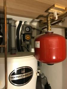
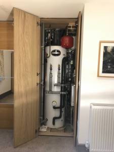
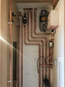
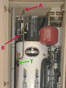
The photos above are showing a very neat installation into a cupboard/wardrobe, implemented by someone who's thought about the pipe layout in advance!
In this case the installation is all the more 'compact' because the solar-thermal components are in the same location as the heat reservoir (the cylinder).
This doesn't have to be the case.
As we saw earlier in the photo posted by @alan-m it is equally permissible to have the solar pump, expansion vessel and safety valves in a loft or similar 'void' in the house.
It's also not essential to buy an insulated box which contains the solar components pre-plumbed.
I assembled my own components and deliberately placed my overflow-reservoir where it was easily accessible in the back-porch.
There's a pipe in a photo from @sunandair which I haven't met before.
I've highlighted it as A here
I'm pretty sure it's an 'expansion pipe' which is open to the air at the top.
[I was wrong. It's another pressure-relief pipe which shares the same tundish. See comment below]
It connects just above the tundish (T) which is open to the air.
A tundish accepts pressurized/hot water from the safety valve on the side of the cylinder and connects to a larger diameter pipe which runs to the outside somewhere.
So I've not previously seen a tundish fitted with an additional air-relief intake pipe above it.
That vertical air-intake also seems to have a side arm "B" which connects to something else.
I'm unsure what that is.
Save energy... recycle electrons!
Posted by: @sunandairapologies for multiple posts - due to rail Wi-Fi file limitations
Does this mean the photos are from a 'training' exercise? 🤔
Save energy... recycle electrons!
Posted by: @transparentThat's another useful set of photos. Thank you @sunandair
It's likely that others will come across this topic in time to come.
So I'm just going to press pause and make a few observations.The photos above are showing a very neat installation into a cupboard/wardrobe, implemented by someone who's thought about the pipe layout in advance!
In this case the installation is all the more 'compact' because the solar-thermal components are in the same location as the heat reservoir (the cylinder).
This doesn't have to be the case.
As we saw earlier in the photo posted by @alan-m it is equally permissible to have the solar pump, expansion vessel and safety valves in a loft or similar 'void' in the house.It's also not essential to buy an insulated box which contains the solar components pre-plumbed.
I assembled my own components and deliberately placed my overflow-reservoir where it was easily accessible in the back-porch.There's a pipe in a photo from @sunandair which I haven't met before.
I've highlighted it as A here-- Attachment is not available --
I'm pretty sure it's an 'expansion pipe' which is open to the air at the top.
It connects just above the tundish (T) which is also open to the air.
A tundish accepts pressurized/hot water from the safety valve on the side of the cylinder and connects to a larger diameter pipe which runs to the outside somewhere.-- Attachment is not available --
So I've not previously seen a tundish fitted with an additional air-relief intake pipe above it.
That vertical air-intake also seems to have a side arm "B" which connects to something else.
I'm unsure what that is.
hi @transparent,
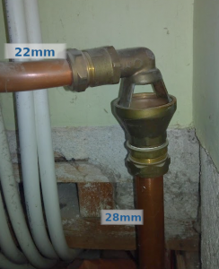
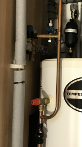
these two pictures might clarify
Pipe A: leads to another pressure relief valve located in the loft which discharges into the tundish . It’s origin branches off the Primary Return pipe of the Heat Pump Primary loop.
branch B: attaches to the valve on the closeup pictured.
@derek-m thanks for that Derek I will look into it after our return journey.
picturs haven’t uploaded easily on this train journey but thank’s for your recommendation. As @transparent said… it’s been more of a “training” journey rather than a “train” journey, with this intermittent WiFi. 😏
Thanks for the additional information and photo's, which are helping to clarify some misconceptions I made earlier. So it is not as I assumed, that the water/glycol mixture actually flows through the collector tubes, but in fact flows through the top header, where thermal energy exchange takes place from the tubes to the mixture.
Your thread has helped to highlight the Achilles Heel of renewable energy sources, which are often not readily available when needed, but can then be in abundance when they are not required.
There are two separate, but connected, aspects to your quandary, the need to keep the temperature within your hot water cylinder within acceptable limits, and the requirement to prevent the collector from overheating.
Your 20 tube collector would appear to have a maximum energy output of 1.2kW under optimal conditions, so would probably take no more than 2 hours to replace the daily heat loss from your cylinder. After 2 hours operation the water temperature in the tank will be increasing, the rate of which will be dependent upon the amount of energy coming from the collector and the volume of water in the cylinder.
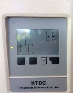
Settings within the MTDC Controller can be used to limit the maximum water temperature within the cylinder, by stopping the mixture from flowing through the collector header, and thereby transferring thermal energy from the collector into the hot water cylinder.
This overcomes the initial requirement to limit the cylinder temperature, but stopping the energy transfer, exacerbates the second problem, since the temperature of the collector will now start to increase. I have not yet found details of the specified maximum temperature limit for the collector, so that is an area you may wish to explore.
I would suggest that you read through the MTDC manual, which may give details of a method to cool the hot water cylinder overnight. The manual for the MTDC5 Controller, that I found, provides details of how the controller can pass the mixture through the collector, when the collector is cooler than the cylinder, which instead of heating the water in the cylinder, actually has a cooling effect. By cooling down at least some of the water within the cylinder will mean that it has more capacity to accept thermal energy when the solar thermal system is operating normally once again.
Below are some test that you could carry out before going on holiday to test how the system responds to different settings.
On the next sunny day, lower the setting of Tmax S2 to see if the solar thermal system is stopped when the cylinder temperature reaches the setting. Then monitor the collector temperature S1, to see how rapidly it increases and how high the temperature may go. Obviously find out the maximum permissible temperature before carrying out this test.
If available on your controller, initiate the overnight cooling to see what effect it has on the water temperature within the cylinder.
Note the settings of any pressure relief valves, which will limit the boiling temperature of any liquids within the system.
Report back on any results obtained for posterity.
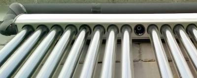
These photos of a vacuum tube might help to demonstrate the principle
The copper tube is held in a plastic 'bung' which seals the open end of the double-glass vacuum envelope.
The inside of the glass envelope heats up. That heat is transferred to a fluid within the long copper tube.
It vapourises and ascends to the bulbous end, which I've smeared with heat-transfer compound.
The glass & copper tube assembly is pushed into a 'pocket' in the manifold, which runs along the top of the 'rack'.
Save energy... recycle electrons!
Thanks for the very thorough feedback Derek. It will be greatly reassuring to have done these tests.
@transparent yes the glass tube system is exactly as per your pictures. And as you say the silicone paste helps transfer the heat to the manifold.
another pause for thought ( for readers who are seeing this for the first time) must be the energy/cost benefit of solar. In so far as: what would be the cost of 6 months of daily DHW heating with a heat pump followed by a bi-weekly legionella cycle for 6 months?! When solar will deliver a fuller hot water tank for free…
- 26 Forums
- 2,396 Topics
- 54.3 K Posts
- 152 Online
- 6,077 Members
Join Us!
Worth Watching
Latest Posts
-
RE: Electricity price predictions
Great point, one of the key ones in my chat with Octopu...
By Batpred , 2 hours ago
-
RE: Running from backup generaor in powercut?
Definitely and professionals sometimes miss it. I had...
By Batpred , 2 hours ago
-
RE: Help me keep the faith with my air source heat pump installation
@batpred Well, I'm running the eBus interface and integ...
By dr_dongle , 4 hours ago
-
RE: Setback savings - fact or fiction?
That´s an interesting point. The combi that we have is ...
By Batpred , 4 hours ago
-
RE: Advice for a novice on Mitsubishi Ecodan 6kW
Hi @green_fox As a we have a PUZ-WM80VAA with FTC7 (...
By RobS , 4 hours ago
-

RE: New Fogstar 15.5kWh upright solution
Let me point out that there are many Chinese suppliers ...
By Transparent , 6 hours ago
-
RE: New Mitsubishi Ecodan 11.2kW installation - L9 errors and maybe more
@jamespa Thanks very much for this, and for mentioning ...
By anotherdaveuk , 6 hours ago
-

RE: Weather compensation- why you should use it
@majordennisbloodnok — The Two Ronnies Mastermind sketc...
By cathodeRay , 6 hours ago
-

RE: Recommended home battery inverters + regulatory matters - help requested
The Regulations specify the export limits in Amps. If...
By Transparent , 7 hours ago
-
RE: ASHP Energy Consumption: Aira 12kW heat pump
@wally Hope your issues are sorted out soon. We have ...
By ChandyKris , 7 hours ago
-
Just realised that this image of the cylinder cupboard ...
By Sheriff Fatman , 10 hours ago
-

RE: Rodents! A word of warning for heat pump owners
Two thoughts: 1: Let's ask @david-s if Primary Pro in...
By Transparent , 10 hours ago
-
RE: Solis S6-EH1P8K-L-PLUS – Why I Chose It and What I’ve Learned So Far
In the diagram below, I describe my understanding of th...
By Batpred , 11 hours ago
-
I need to have a look out for it. I know IBM feeds some...
By Batpred , 11 hours ago
-
RE: Heat pump not reaching flow temperature
is the house warm enough?
By davidnolan22 , 16 hours ago
-
RE: Daikin Atherma ASHP Cycling 6 Times an Hour?
Thanks for your reply. Yes that's a good idea to try a...
By John Marshall , 17 hours ago
-

RE: Hot water heating in parallel with space heating
An external heat exchanger would need a pump which woul...
By bontwoody , 17 hours ago
-
RE: Gen 6 Samsung ASHP losing 20C of DHW in 60 min directly after generation
@ecobaker Thanks for this. I've had it in both slots. ...
By andbeck , 1 day ago
-

RE: Air source heat pump circuit not operational
Welcome to the forums. If the thermostat shows it’s c...
By Mars , 1 day ago

