Posted by: @iantelescopeRelaxation............................., discussing the Technical details of Heat Pumps .............................Not the Politics!
Losses..........................the causes
Heat Pump or Heat Exchanger loss?
I accept the comments about the source of my losses in my Heat Pump.
Yes, The Losses are "caused" , in part, by the Heat Pump having to increase the pipe water Temperature to allow the Heat Exchanger to supply an increased Water Temperature to the Radiator Circuit.
But, If the Heat were not installed there would be no need to increase the Heat Pump output Water Temperature in the first place!
Loss to my kitchen
With my Heat Exchanger being installed in my kitchen I also accept the comments about the heat loss being used to heat the kitchen.
Yes, The Heat Exchanger Heat Loss will heat my kitchen...........but I do not live in the kitchen.
The Heat exchanger heat loss should be diverted to my cold winter living room.
Range of the compressor Inverter power
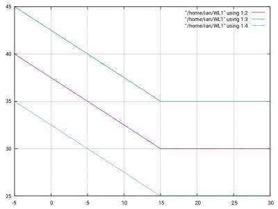
My Heat pump fails to provide enough heat when the outside temperature descends below -3 C.
My Heat pump "short Cycles" when the Outside Temperature approaches +15 C, caused by the inability of the Inverter to provide a minimum Compressor power.
What is the Ratio of the Maximum available power to Minimum available power for my Samsung Heat Pump ?
Loss due to Buffer tanks
My Heat Pump is fitted with a valve allowing me to use or not use a 50 l buffer tank.
When used , the Buffer tank consumes , or looses , circa 10% to my kitchen.
The tank , installed to reduce "Short Cycling" has little effect upon my "Short Cycling" but never the less consumes , or looses yet more energy!
ian
I and, I am sure others, understand and sympathise with your concerns. Perhaps misguidedly, I (and I am sure others) are trying collectively to pin down the source of the 25% inefficiency which you believe you have in order, again perhaps misguidedly, to try to help and improve the situation.
However, you clearly understand much if not all of it anyway, so perhaps you neither need nor want help, but just wish to record your feelings. If so then that's fair enough.
If you do want any advice, given freely and in good faith, then please say so in order that there is no ambiguity, and also offer up some of the data requested. Otherwise I wish you well in your quest to improve matters.
4kW peak of solar PV since 2011; EV and a 1930s house which has been partially renovated to improve its efficiency. 7kW Vaillant heat pump.
Posted by: @derek-mPosted by: @jamespaPosted by: @derek-mAs you have discovered, there appears to be no mechanism for consumers to get poorly installed and commissioned systems rectified.
Isn't this what MCS is supposed to do. Government, as I understand it, view them as the mechanism to ensure standards are maintained and they speak extensively of consumer protection. If they don't do this then....
As far as I am aware, MCS set standards and charges installer's for accreditation, but no one actually appears to inspect and sign off installations, hence the number of 'cowboys' out there.
I guess my comment was a little tongue in cheek, but I do believe that MCS are seen by Government and others as the mechanism by which standards are maintained in reality, not just on paper.
Sadly there seems to be significant evidence to the contrary.
4kW peak of solar PV since 2011; EV and a 1930s house which has been partially renovated to improve its efficiency. 7kW Vaillant heat pump.
Hi Derek,
Water Temperatures
My Heat Pump was "designed" for a system without a heat exchanger !
The Radiator circuit was "designed " and selected for water temperatures between 35 C and 45 C by three different companies.
The system was supplied with a Heat Exchanger where the Temperature drop between the Output Water Temperature and the Radiator circuit is 11-14 C !
Consequently , the Radiators are fed with water between 26C and 32 C when "designed" for temperatures between 35 C and 45 C.
Short Cycling
The Heat Pump was fitted with a 50 l Buffer Tank to reduce Short Cycling.
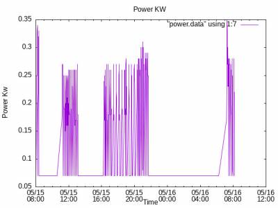
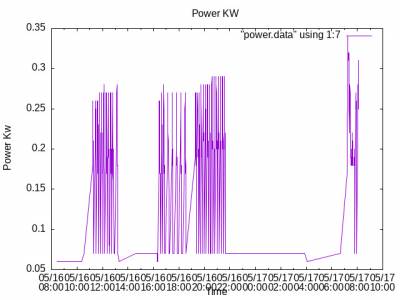
This is the result in may 2023.
The Short cycling period of these , and numerous others is 10.5 mins.
This cycling is repeated up to 80 times per day, resulting, I believe , in the production of Black Ink in the Water supply.
Black Ink and Short Cycling
.With the Manufacturers , Samsung and Telford, calling for the annual inspection and service I investigated the water quality under BS7593:2019.
The Water was cleaned in both the Heat Pump and Radiator Water circuits at a cost of £600.
ian
Posted by: @iantelescopeHi Derek,
Water Temperatures
My Heat Pump was "designed" for a system without a heat exchanger !
The Radiator circuit was "designed " and selected for water temperatures between 35 C and 45 C by three different companies.
The system was supplied with a Heat Exchanger where the Temperature drop between the Output Water Temperature and the Radiator circuit is 11-14 C !
Consequently , the Radiators are fed with water between 26C and 32 C when "designed" for temperatures between 35 C and 45 C.
Short Cycling
The Heat Pump was fitted with a 50 l Buffer Tank to reduce Short Cycling.
This is the result in may 2023.
-- Attachment is not available --
-- Attachment is not available --The Short cycling period of these , and numerous others is 10.5 mins.
This cycling is repeated up to 80 times per day, resulting, I believe , in the production of Black Ink in the Water supply.
Black Ink and Short Cycling
.With the Manufacturers , Samsung and Telford, calling for the annual inspection and service I investigated the water quality under BS7593:2019.
The Water was cleaned in both the Heat Pump and Radiator Water circuits at a cost of £600.
ian
What control do you have on the system.
Make and model pls
Heat pump installer
Posted by: @iantelescopeThis is the result in may 2023.
I cant remember exactly the temperature in May but I would doubt that there are many systems that do not cycle at that time of year, simply because the heat demand is so low relative to the demand mid winter. I cant make out the mark-space ratio to get a feel for what your actual demand is.
10.5mins is obviously the programmed-in minimum cycle time and clearly the addition of 50l extra system volume wasn't enough to extend the time that it takes to heat the engaged system water volume to more than this programmed in minimum. Again in May perhaps not so surprising, there will likely be a period of the year when it does make a difference.
It may well help to adjust the min cycle time parameter, increase the permitted flow temp hysterisis or just run the heat pump in the same way as you would run a gas boiler at this time of year, ie off at night and during the peak of the day, on only during the morning and early evening at either end of the season.
Posted by: @iantelescopeThe system was supplied with a Heat Exchanger where the Temperature drop between the Output Water Temperature and the Radiator circuit is 11-14 C !
OK so that alone easily explains a 20-30% efficiency penalty, perhaps more. A heat exchanger, correctly plumbed and sized, should not have anything like this 'approach temperature'. My guess its either too small, plumbed the wrong way round or the pumps either side are poorly matched. Have you got glycol on the heat pump side, or have you got antifreeze valves?
4kW peak of solar PV since 2011; EV and a 1930s house which has been partially renovated to improve its efficiency. 7kW Vaillant heat pump.
It is obvious from the data you have supplied that your system will struggle to achieve the correct indoor temperatures during cold weather periods. Do you have any TRV's installed on your radiators? If so, are they all fully open?
Have your radiators been balanced to match the heat loss of each room using the lockshield valves?
Do you have any thermostats within your system and what is their temperature setting?
Cycling will occur during milder weather conditions, but if it is more than 6 times per hour it is deemed to be short cycling. Various aspects may lead to short cycling.
The fact that the thermal energy is not being transferred efficiently to the radiators, means that the rooms are heating at a slower rate so the heat pump is likely to be operating for a longer period.
Because the loading on the heat pump is lower than it should be, it will exceed the desired LWT quicker and stop the compressor. But because the LWT is higher than necessary it will probably cool down quicker and restart the compressor, hence the short cycling. I would suggest that you have a look at the heat pump controller settings and see if it is possible to make the difference between the switch on temperature and switch off temperature as wide as possible.
Did your installer explain why the heat exchanger was installed in the first place and if it is possible to have it removed?
Sound like your have a TPI third party controller on the system.
Heat pump installer
A Samsung Report on my Heat Pump ...............
In March 2023, A French Samsung Engineer arrived to perform an "independent report on my System for my Installer!!
Short Cycling
1: Short Cycling
The Water Flow rate on both water circuits was "excessive" , and, would have to be reduced.
The Water Flow rate is controlled by two Pulse Width Modulated , PWM motor controls.
Neither PWM was connected with a cable which can only be obtained from Germany.
2: Grundfoss UPM3 PWM motor output from Controller PCB.
I , having obtained the missing cables, pointed out that no signal was being output from the Controller PCB.
I asked why , this, and other Samsung owners had found these faults.
The French Engineer said that he was aware of these problems , pointing out that Flow Rate PWM control was essentially an option.
3:Grundfoss UPM3 PWM motor input on Radiator water circuit
The French Engineer could not explain where the PWM input was to be connected.
4: The French Samsung Engineer was quite frank in saying that "only the Germans REALLY knew how the Samsung's work!!"
5: Samsung 2091 options 2,3 and 4
The French Engineer frankly said that "he did not know what the Samsung Option 2091 options 2, 3 and 4 did, but he thought ..........not much".
I suspect that 2091 option 2,3 and 4 control the Cycle times.
The Samsung control option 2091 option 4 seems to adjust the Cycle time by pulsing the Primary Grundfoss motor On and OFF producing my 10.5 minute cycle time.
5: User Water Rate control
Having previously obtained both PWM cables from Ebay-Germany I programmed an "Arduino" to send PWM Signals to both motors.
Both Grundfoss motors work flawlessly.
The French Samsung Engineer's report has never been delivered , being blocked ( or "lost" ) by my "installer" .
C'est la vie !
My "installer" appears to have fired their Engineer who got the French Samsung Engineer.
Yet Again..............."please don't shoot the message boy ..........he did not write the message"
Heat Exchanger?
Heat Pump matching to Radiator load.
1: My Heat Pump was designed for a Radiator circuit requiring a 6 kW Heat pump without a Heat Exchanger.
2: A 5 kW Heat Pump was delivered complete with an unwanted Heat Exchanger .
3: The Heat Exchanger, dividing the designed water circuit in two , requires two motors on either side of the Heat Exchanger.
4: Both motors are Grundfoss UPM3 Pulse width modulated water flow motors.
5: Neither PWM motor was supplied with a PWM control cable , given that PWM is an "option".
6: The Grundfoss PWM motors run flawlessly when driven by a "Arduino".
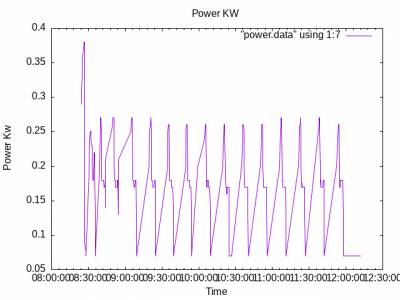
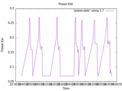
7: Varying the Flow rate as a function of room temperature better matches the Heat Pump Water output to the Radiator load ,
The System with PWM control gives a cycle time of 14.1 minutes :
On controlling the water flow rate as a function of room temperature gives a maximum cycle time of 24 minutes!:
A comment, by a visiting French Samsung Engineer, was correct in saying that the "Cycle time is too short because the water flow rate is excessive".
I would add that the water flow rate is uncontrolled!
ian
Hi Ken,
Many thanks for your advice..........
Changing +15 C and -3C parameters
I never thought of changing the + 15 C specification on my Weather compensation ( called Water Law by Samsung ) curve!
I will certainly give it a try.
I have changed the -4 C parameter to -5 C on my Water Law curve as recommended by Samsung for Scotland.
Unfortunately, my Heat Pump was not designed by anybody ........................it just "fell off the back of a lorry complete with an unwanted, and unplanned, heat exchanger!"
You have restored my confidence in "installers"............ a difficult operation given the behaviour of my current "installer".
ian
Posted by: @iantelescope
Heat Exchanger?
Heat Pump matching to Radiator load.
1: My Heat Pump was designed for a Radiator circuit requiring a 6 kW Heat pump without a Heat Exchanger.
2: A 5 kW Heat Pump was delivered complete with an unwanted Heat Exchanger .
3: The Heat Exchanger, dividing the designed water circuit in two , requires two motors on either side of the Heat Exchanger.
4: Both motors are Grundfoss UPM3 Pulse width modulated water flow motors.
5: Neither PWM motor was supplied with a PWM control cable , given that PWM is an "option".
6: The Grundfoss PWM motors run flawlessly when driven by a "Arduino".
7: Varying the Flow rate as a function of room temperature better matches the Heat Pump Water output to the Radiator load ,
The System with PWM control gives a cycle time of 14.1 minutes :
-- Attachment is not available --
On controlling the water flow rate as a function of room temperature gives a maximum cycle time of 24 minutes!:
-- Attachment is not available --
A comment, by a visiting French Samsung Engineer, was correct in saying that the "Cycle time is too short because the water flow rate is excessive".
I would add that the water flow rate is uncontrolled!
ian
Good work.
I think if this were my system then I would take the following approach to the heat exchanger and buffer:
Heat exchanger:
First ask - is it necessary? If you have glycol on the HP side to stop freezing then the purpose is to reduce the amount of glycol needed (because you only need to put glycol in the interior water). That doesn't mean its necessary but it is a reason to fit a HEX
If you have antifreeze valves and don't have glycol then, unless you have something very odd in your system, it probably has no purpose.
If you conclude it has no purpose Id take it out, perhaps initially by bypassing so it can be reinstated.
If you conclude it does have a purpose then it needs to be set up correctly as the French Samsung engineer implies.
- Firstly make sure its plumbed correctly. The incoming water from the heat pump should meet the outgoing water to the radiators. That way you get the lowest possible approach temp (temperature drop across the heat exchanger).
- Having ensured its plumbed correctly you need to set up the pumps. I don't know if samsung heat pumps can control two pwm pumps, if they can then getting it to do so would be the way forward.
- If the Samsung HP cant control two pumps then you need to set up both pumps to pump at the correct speed, which is the speed needed to deliver ~5kW (or whatever the actual max output of the HP is) through whatever size flow pipes you have, at a delta T of (probably) 5C, or a bit more. If you have glycol one side and water the other, then remember that the heat capacity of glycol is less than that of water so the flow rate on the HP side will need to be faster than the flow rate on the emitter side.
- You can dot his by measuring flow rates, or by aiming for a deltaT of 5C from flow to return (when its cold outside) either side of the HEX.
- By now you may have decided that removing the heat exchanger and fitting antifreeze valves (if they aren't already present) is anyway simpler!
Buffer tank?
First discover - is it plumbed 2, 3 or 4 pipe and is it plumbed in the return or the flow
If its plumbed 2 pipe in the return, then its unlikely to do any harm apart from the heat lost from it to a room you don't want to heat. Perhaps you can turn down the emitter in that room or insulate the tank
If its plumbed any other way than 2 pipe in the return, it will compromise efficiency so should not be fitted unless necessary. I would simply bypass it and only reinstate it when you find a good reason to do so.
Hope that helps.
Overall I would be aiming for the simplest system that works and the minimum temperature drop across any buffer/HEX (and certainly no more than 5C total). That would be a starting point from which to tweak.
4kW peak of solar PV since 2011; EV and a 1930s house which has been partially renovated to improve its efficiency. 7kW Vaillant heat pump.
Many many thanks James.
Heat Exchanger
I completely agree with you, the Heat-exchanger fitted to my system should be removed.
I would remove the Heat Exchanger myself ......were it not for the threats from my "installer".
Lèse-majesté
Buffer Tank
My Buffer tank was fitted, by my "installer" across the Input ports of the Heat Exchanger.
My Buffer was originally "designed" by Samsung-Dalliam to be fitted on the HP Water return to "protect the System against frost damage".
My "installer" attacked Samsung , saying that "Samsung's intervention was ludicrous" and his "boys would do the job".
The installer's "engineers" arrived, two months later, but said that they "did not where to install the Buffer."
Buffer tank for Freezing OR for "Short Cycling"
My Buffer tank was , originally, supposed to to fitted "in series" on the HP Water input , to reduce Short Cycling.
However, Samsung-Dalliam tried to solve my other problem , Freezing pipes, by recommending the installation of the Buffer on the Water HP return.
My "installer" fitted the Buffer across the Heat Pump after expressing the view "that he did not know What the Buffer was doing nor where it should be installed".
Buffer Tank removal
Again I would remove the Buffer tank were it not for the threats from my "installer".
I have had three different Buffer positions suggested to solve the "Short Cycling" and "freezing".
The "Freezing problem resulted in a two meter deep dense cloud covering an area of 64 square meters with a 3-4 kWh energy consumption....!
Lèse-majesté
ian
- 27 Forums
- 2,495 Topics
- 57.8 K Posts
- 343 Online
- 6,220 Members
Join Us!
Worth Watching
Latest Posts
-
RE: What determines the SOC of a battery?
@batpred I didn't write the Seplos BMS software, I a...
By Bash , 12 minutes ago
-

RE: Electricity price predictions
Sorry to derail this thread ‘slightly?’ but back to the...
By Toodles , 22 minutes ago
-

RE: Humidity, or lack thereof... is my heat pump making rooms drier?
Without knowing it, @andrewj, you've laid down the gaun...
By Majordennisbloodnok , 41 minutes ago
-
RE: Testing new controls/monitoring for Midea Clone ASHP
@tasos and @cathoderay thanks. I have some history grap...
By benson , 45 minutes ago
-

I am having my existing heat pump changed to a Vaillant...
By trebor12345 , 1 hour ago
-
Our Experience installing a heat pump into a Grade 2 Listed stone house
First want to thank everybody who has contributed to th...
By Travellingwave , 2 hours ago
-
RE: Setback savings - fact or fiction?
@cathoderay The input power is largely determined by...
By RobS , 2 hours ago
-

RE: Solis inverters S6-EH1P: pros and cons and battery options
Just to wrap this up here for future readers: The S...
By Batpred , 4 hours ago
-
RE: Struggling to get CoP above 3 with 6 kw Ecodan ASHP
Welcome to the forums.I assume that you're getting the ...
By Sheriff Fatman , 4 hours ago
-
RE: Say hello and introduce yourself
@editor @kev1964-irl This discussion might be best had ...
By GC61 , 6 hours ago
-

@painter26 — as @jamespa says, it's for filling and re-...
By cathodeRay , 10 hours ago
-

RE: Oversized 10.5kW Grant Aerona Heat Pump on Microbore Pipes and Undersized Rads
@uknick TBH if I were taking the floor up ...
By JamesPa , 20 hours ago
-

RE: Getting ready for export with a BESS
I would have not got it if it was that tight
By Batpred , 22 hours ago
-
RE: Need help maximising COP of 3.5kW Valiant Aerotherm heat pump
@judith thanks Judith. Confirmation appreciated. The ...
By DavidB , 1 day ago
-

RE: Recommended home battery inverters + regulatory matters - help requested
That makes sense. I thought better to comment in this t...
By Batpred , 1 day ago
-
Bosch CS5800i 7kW replacing Greenstar Junior 28i
My heat pump journey began a couple of years ago when I...
By Slartibartfast , 1 day ago
-

RE: How to control DHW with Honeywell EvoHome on Trianco ActiveAir 5 kW ASHP
The last photo is defrost for sure (or cooling, but pre...
By JamesPa , 1 day ago
-

RE: Plug and play solar. Thoughts?
Essentially, this just needed legislation. In Germany t...
By Batpred , 1 day ago
-
RE: A Smarter Smart Controller from Homely?
@toodles Intentional opening of any warranty “can of wo...
By Papahuhu , 1 day ago
-
RE: Safety update; RCBOs supplying inverters or storage batteries
Thanks @transparent Thankyou for your advic...
By Bash , 1 day ago
-
RE: Air source heat pump roll call – what heat pump brand and model do you have?
Forum Handle: Odd_LionManufacturer: SamsungModel: Samsu...
By Odd_Lion , 1 day ago
-
RE: Configuring third party dongle for Ecodan local control
Well, it was mentioned before in the early pos...
By F1p , 2 days ago
-

RE: DIY solar upgrade - Considering adding more panels
I know this is a bit old, but it made me wonder what co...
By Batpred , 2 days ago

