Hi Derek,
I Stand Corrected, you are right!, I now understand what has happened to my Heat Pump!
***************************************************************************************************************************
*************** The Parallel Kensa Tank should be positioned before the motor ***********************
************************************************************************************************************************
********************************************************************************************
Difference between an Electrical Capacitor and an Buffer Tank.
In an electrical system the Current is a controlled by the Voltage, Ohms law .
whereas
In an Water system the Current is controlled , and set by a Motor.
*************************************************************************************************
Your excellent summary of the causes of "Short Cycling" corresponds to my own understanding of the problem.
As to the solution , you have again made an excellent summary of my attempts to rectify the situation.
System Modifications
1) Increase the Pipe Volume on the Primary side of the Heat Exchanger.
This was initially designed by Samsung-Dallium who specified the installation of a 50L Tank on the primary side of the Heat Exchanger.
Samsung-Dallium then changed the problem to that of "protecting the Heat Pump from the "Freezing Temperatures" experienced in Scotland.
Samsung-Dallium attempted repair was then were then described as "Ludicrous " by my Installer" who would send "his boys" to install the Buffer Tank.
My "installer " then appeared some two months later saying that "they did not know where the Tank was to be installed".
My "installer" then installed the Tank according to the Kensa Instructions.
2) Cycle Time modification.
My Samsung has a control instruction , Field bit 2091, with several options attached.
The Fourth option 2091 Opt4 controls both motors by operating a sequence of delayed switching of the Motors.
3) Motor delays , 2091 option 4
Currently, After the Compressor has stopped the motors remain fully ON for 3 minutes.
Then switch OFF for three minutes.
Then switch ON for Three minutes ......on so on ................
These motor pulses are designed to control , and extend the cycle time, and, are readily apparent on the Samsung Water Temperature Display.
4) Balancing Energy supply to Energy Consumed.
I have reduced the load by experimentally limiting the heating of my Living room ONLY.
The Cycle Time increase considerably when the Energy Demand equals the Energy produced at minimum output compressor power 1.25 kW.
5) Difference between an Electrical Capacitor and an Buffer Tank.
I Stand Corrected, you are right, I will need to stand in the corner!
In an electrical system the Current is a controlled by the Voltage.
whereas
In an Water system the Current is controlled , and set by a Motor.
The Parallel Kensa Tank should be positioned before the motor.
ian
Mounted in parallel with the PHE, the buffer tank is more like having a low value resistor in parallel with a higher value resistor (PHE). Most of the current (water flow) is therefore going through the buffer tank rather than the PHE. I suspect that this will make the short cycling worse rather than better, since there will be less thermal energy demand.
You could try the following when the weather is a little cooler.
Make certain that all your radiators are in use to provide maximum thermal energy demand.
Set your heat pump at a fixed LWT of 35C.
Open the isolation valve so that flow can go through the buffer tank.
Run your system and measure the flow and return temperatures on the primary and secondary sides of your PHE.
Time the frequency of the starting and stopping of your heat pump.
Close the isolation valve to prevent flow through the buffer tank then repeat the above test.
Post the results of both tests.
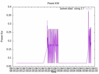
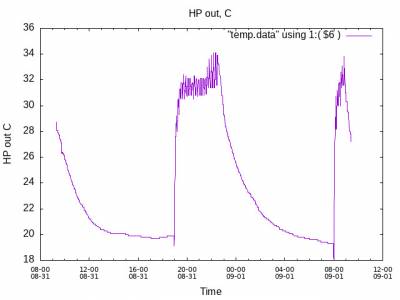
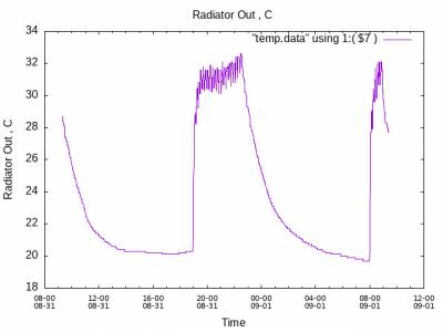
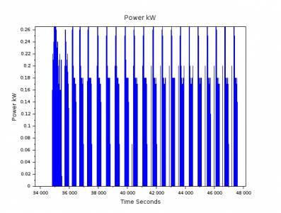
I have measured and recorded
1) Power on 31-08-31
2) HP Motor Water input Temperature ( K Type), on 31-08-31
3) Radiator_OP Water Temperature( K Type) , on 31-08-31
4) Cycle_Time, derived from Power, on 31-08-31
These recordings were taken without the Buffer tank OR without Water Heating.
Cycle Time on 31-08-23
The Average cycle time is her the "standard " for the summer, 10.5 minutes.
Conclusions
1) The Samsung Display of the Water Temperature was > 39 C , while that appearing at the HP Motor was 32.5 C reflecting the large drop across the HP Pipework of 6.5 C.
2) The Radiator output Temperature was 31.5 a drop 1 C across the Heat Exchanger!
3) The Water Temperature at the Principal Radiator in my living room was 28 C , giving a total drop of 11 C from that displayed on the Samsung.
4) These readings are a improvement of the drop of 14 C experienced during winter.
These Recordings were made on 31-Aug-2023.
The Other significant variable is the control of the Water Rate.
The Water rate PWM output from the Samsung Controller board does not work, and, I am using my own "Arduino" PWM Control.
Finally, The System is configured for "Weather compensation otherwise known as the Samsung-Water Law .
I will go through all of the available Parameters ......Buffer Tank, PWM , Weather Compensation, Water Heating et al but it will take some time.
ian
How are you obtaining and recording the data for the graphs?
On the Power kW graph, what is the scaling of the horizontal axis? Is that 2000 second intervals? Please explain the kW scaling which seems quite low.
Posted by: @iantelescope1) The Samsung Display of the Water Temperature was > 39 C , while that appearing at the HP Motor was 32.5 C reflecting the large drop across the HP Pipework of 6.5 C.
Are you certain of 6.5C, Have you checked the actual temperature at the output of the Samsung?. If so, are the pipes insulated and are the flow rates sufficient?
Posted by: @iantelescope2) The Radiator output Temperature was 31.5 a drop 1 C across the Heat Exchanger!
What do you mean by 'radiator output temperature' output from the PHX or output from the radiators
Posted by: @iantelescope3) The Water Temperature at the Principal Radiator in my living room was 28 C , giving a total drop of 11 C from that displayed on the Samsung.
Thats a big drop. Are your flow rates sufficient? Low flow will cause high drop in pipes.
Posted by: @iantelescopeThe Average cycle time is her the "standard " for the summer, 10.5 minutes.
Not really surprising in August!
Was the volumiser/buffer in circuit or out of circuit?
4kW peak of solar PV since 2011; EV and a 1930s house which has been partially renovated to improve its efficiency. 7kW Vaillant heat pump.
I ,again , must stand in the corner ......corrected!
In electronics the Current, through a resistance is proportional to the voltage across the resistance.
Whereas
In Water the Current, through a resistance, here the Heat Exchanger is not proprotional to the Water Temperature!.
Both the Electrical Capacitor and the Water Buffer are used as Integrators.
The Electrical Capacitor accumulates, or integrates charge in Coulombs.
The Water Buffer accumulates, or integrates , Energy in Joules !
The Water Buffer is here used as an integrator to smooth out the noise on the Water Cycle!
The Buffer tank presents a water resistance lower than the Heat Exchanger resulting in most of the water flowing through the Buffer.
However, the switch can increase the resistance of the path through the Tank thereby increasing the flow through the Heat Exchanger.
My concern is with the description of the water in Heat Pump in a continuous
"this wee thing goes up resulting in this other wee thing going down by a wee bit" description.
Surely we can get a better system description .......where we can apply something like PSpice , Mathematica......!
ian
Posted by: @iantelescopeIn Water the Current, through a resistance, here the Heat Exchanger is not proprotional to the Water Temperature!.
In the analogy you are trying to draw, the voltage is the pump head (pressure) not the water temperature. The flow rate is the current and the impedance is the friction in the pipes.
4kW peak of solar PV since 2011; EV and a 1930s house which has been partially renovated to improve its efficiency. 7kW Vaillant heat pump.
Sorry , James , I am proposing a model of Energy , in Joules , and Power in Watts, not Pressures and Flow rates.
I am proposing a model of Heat Energy in Joules .
In this model Sources would be modelled in watts, where a Watt is a Joule per second.
Given that the energy dissipated in a pipe :
Power ( Watts) = Specific_Heat X Delta_T X Flow_Rate ( Litres per second)
then, a length of pipe could be modelled as a "Water Resistance" dissipating power analogous to the dissipation in an electrical resistance.
Water buffers would be modelled as Integrators .
A system model could be produced on the free Linux "Scilab"!
ian
Am I Sure of Temperatures ?
No, I am sure of nothing!
The Water Temperatures are measured , in the main , by Chinese K Type sensors of poor quality , measuring the Temperatures on the outside of the copper pipes.
The External Temperature measurement is another, of innumerable objections.
The Heat Pump is covered by a spiders web of Copper with each K type being interfered by it's neighbour!
Flow rates and Temperature Drops?
In pipes ,water Power Loss is proportional to flow rate.
The visiting French Samsung Engineer said that "the flow rates are excessive ....causing the Temperature drops.
I have therefore reduced the flow rates to reduce the Temperature Drops across the pipes.
Flow rates and PWM Control
I asked the French Engineer how I was to reduce the flow rates given that the PWM signal from the control board was faulty.
The Flow rates being , optionally, controlled by the PWM input to the HP Grunfos motor..........
On being told that I had obtained the PWM Signal cables in Germany , he replied that
" Only the Germans REALLY understand How the PWM System works!".
The French engineer made no attempt to try the PWM System merely saying that he did not understand the PWM system.
The German "Sharky"
I Fitted a German , Danfos , Water Power meter to overcome the objections to the K type sensors.
The Sharky measures the actual ,in water , Temperatures, Flow rate , Delta_T , Power and Energy.
ian
Posted by: @iantelescope
Sorry , James , I am proposing a model of Energy , in Joules , and Power in Watts, not Pressures and Flow rates.
I am proposing a model of Heat Energy in Joules .
In this model Sources would be modelled in watts, where a Watt is a Joule per second.
Given that the energy dissipated in a pipe :
Power ( Watts) = Specific_Heat X Delta_T X Flow_Rate ( Litres per second)
then, a length of pipe could be modelled as a "Water Resistance" dissipating power analogous to the dissipation in an electrical resistance.
Water buffers would be modelled as Integrators .
A system model could be produced on the free Linux "Scilab"!
ian
Sorry but the analogy doesn't work. Pipes convey heat from one end to another according to your equation, they don't dissipate it according to this equation.
To the extent that pipes do dissipate heat (which should be small) its proportional to their surface area and the temperature difference between the water in the pipe and the surrounding air/medium.
Posted by: @iantelescopeThe visiting French Samsung Engineer said that "the flow rates are excessive ....causing the Temperature drops.
Thats just nonsense. Faster flows through a pipes give a lower temperature drop along its length. Was the french guy a plumber?
Posted by: @iantelescopeNo, I am sure of nothing!
OK well thats unfortunate.
I suggest you get back to basics, disable the buffer untill it has been correctly plumbed, measure some temperatures with some certainty if you can, leave some TRVs open to ensure system volume. But none of this can be done in the current UK weather! Given this, and if the NIC person is visiting soon, its probably best to do nothing until he has been.
4kW peak of solar PV since 2011; EV and a 1930s house which has been partially renovated to improve its efficiency. 7kW Vaillant heat pump.
Posted by: @iantelescope
Flow rates and Temperature Drops?
In pipes ,water Power Loss is proportional to flow rate.
The visiting French Samsung Engineer said that "the flow rates are excessive ....causing the Temperature drops.
I have therefore reduced the flow rates to reduce the Temperature Drops across the pipes.
ian
Was this French guy actually an engineer or had any form of training.
The pressure from the pump pushes the water along the pipework. The greater the pressure differential the greater the flow rate. The thinner the pipework the greater the pressure required to push the same quantity of water along the pipe.
If the water temperature at the inlet end of a pipe is greater than the temperature at the outlet end, then it would indicate to me that the flow rate down the pipe is much too low rather than too high.
Water flowing down a well insulated pipe should lose very little temperature since it will be flowing quite quickly in the great scheme of things. When this water enters a radiator which has a much greater volume, the flow rate falls quite dramatically, hence the water has much longer to dissipate thermal energy into the radiator and hence the room.
If you are getting 'true' large temperature differences along pipes, this would indicate that there is little or no flow taking place.
Temperature Drop and flow rate
Again, James you are probably correct.
However, my "intuition" is still basically that of an Electrical/Electronic Engineer.
I , and I suspect the French Samsung Engineer, would , instinctively, consider a pipe Temperature drop to be proportional to the flow rate.
So much for intuition!
Time for a system model?
A system model , implemented in Scilab, would surely be preferable!
Temperature Measurement ?
The German Sharky does give me the actual Temperatures and flow rates within the pipe water.
However, The Sharky only measures the water temperature , in my case , at the start of the Radiator circuit.
At a cost of £300 this is definitely a one off , unmoveable , expense.
Currently I only use the front panel of the Sharky.....the RS485 output lines will have to wait until I can afford them!
After nearly 18 months of this , I , a 75 year old, am exhausted and broke.
Promised to cost "no more than £20 a month " this Heat Pump has now, so far, cost me £ 9000 with a record 70% increase in my Real Winter Electricity consumption.
ian
- 27 Forums
- 2,495 Topics
- 57.8 K Posts
- 301 Online
- 6,220 Members
Join Us!
Worth Watching
Latest Posts
-

RE: Electricity price predictions
@skd I think your guess might well be right - unfortuna...
By Toodles , 4 minutes ago
-
RE: Humidity, or lack thereof... is my heat pump making rooms drier?
@majordennisbloodnok I’m glad I posted this. There see...
By AndrewJ , 15 minutes ago
-
RE: What determines the SOC of a battery?
@batpred I didn't write the Seplos BMS software, I a...
By Bash , 2 hours ago
-
RE: Testing new controls/monitoring for Midea Clone ASHP
@tasos and @cathoderay thanks. I have some history grap...
By benson , 2 hours ago
-

I am having my existing heat pump changed to a Vaillant...
By trebor12345 , 3 hours ago
-
Our Experience installing a heat pump into a Grade 2 Listed stone house
First want to thank everybody who has contributed to th...
By Travellingwave , 3 hours ago
-
RE: Setback savings - fact or fiction?
@cathoderay The input power is largely determined by...
By RobS , 4 hours ago
-

RE: Solis inverters S6-EH1P: pros and cons and battery options
Just to wrap this up here for future readers: The S...
By Batpred , 6 hours ago
-
RE: Struggling to get CoP above 3 with 6 kw Ecodan ASHP
Welcome to the forums.I assume that you're getting the ...
By Sheriff Fatman , 6 hours ago
-
RE: Say hello and introduce yourself
@editor @kev1964-irl This discussion might be best had ...
By GC61 , 7 hours ago
-

@painter26 — as @jamespa says, it's for filling and re-...
By cathodeRay , 11 hours ago
-

RE: Oversized 10.5kW Grant Aerona Heat Pump on Microbore Pipes and Undersized Rads
@uknick TBH if I were taking the floor up ...
By JamesPa , 22 hours ago
-

RE: Getting ready for export with a BESS
I would have not got it if it was that tight
By Batpred , 24 hours ago
-
RE: Need help maximising COP of 3.5kW Valiant Aerotherm heat pump
@judith thanks Judith. Confirmation appreciated. The ...
By DavidB , 1 day ago
-

RE: Recommended home battery inverters + regulatory matters - help requested
That makes sense. I thought better to comment in this t...
By Batpred , 1 day ago
-
Bosch CS5800i 7kW replacing Greenstar Junior 28i
My heat pump journey began a couple of years ago when I...
By Slartibartfast , 1 day ago
-

RE: How to control DHW with Honeywell EvoHome on Trianco ActiveAir 5 kW ASHP
The last photo is defrost for sure (or cooling, but pre...
By JamesPa , 1 day ago
-

RE: Plug and play solar. Thoughts?
Essentially, this just needed legislation. In Germany t...
By Batpred , 1 day ago
-
RE: A Smarter Smart Controller from Homely?
@toodles Intentional opening of any warranty “can of wo...
By Papahuhu , 1 day ago
-
RE: Safety update; RCBOs supplying inverters or storage batteries
Thanks @transparent Thankyou for your advic...
By Bash , 1 day ago
-
RE: Air source heat pump roll call – what heat pump brand and model do you have?
Forum Handle: Odd_LionManufacturer: SamsungModel: Samsu...
By Odd_Lion , 1 day ago
-
RE: Configuring third party dongle for Ecodan local control
Well, it was mentioned before in the early pos...
By F1p , 2 days ago
-

RE: DIY solar upgrade - Considering adding more panels
I know this is a bit old, but it made me wonder what co...
By Batpred , 2 days ago

