Help me optimise my ASHP Pipework
I've got a Nibe F2040 ASHP which has been installed for over a year now.
Whilst trying to optimise the system I've wondered if the buffer is causing me issues.
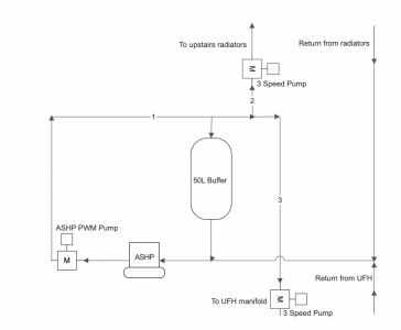
See attached drawing of my system. I have noticed that the pipework at point '1' is cooler than at point '2' and '3'.
The PWM motor is controlled by the Heat Pump to maintain a deltaT and the other 2 pumps are fixed speed (currently setting 2).
Does anyone have any suggestions on how I can better match the circulation pumps to the HP, or how I can prevent the mixing in the buffer.
I'm tempted to ask my installer to add a couple of valves to the top and bottom of the buffer so I can try isolating this completely?
I would suggest that you check your schematic, since it appears to make little sense. A buffer tank would normally have at least 4 connections, 2 in and 2 out. I also don't understand why pipe '1' would be cooler than pipes '2' and '3', if the direction of flow is as shown.
There is often an arrow on the pump body to indicate the direction of flow.
The schematic is correct as drawn and the buffer is Tee'd off the pipework that then goes towards the other 2 pumps.
Apologies pipe '1' was meant to say warmer not cooler.
What is the temperature difference?
Looking at the schematic, I suspect that the combined flow rate through the two pumps on pipes '2' and '3' is greater than the pump on pipe '1'. This will probably have the effect of drawing the cooler water in the return pipe, through the buffer tank, and hence causing it to mix and cool the water from the heat pump. Try reducing the speed of the pumps on pipes '2' and '3' to see if this increases the temperature in the aforementioned pipes.
@luke remove the buffer and it will work properly. The schematic is not a Nibe 2040 configuration. There is no need for the buffer. If you have a blending valve and pump on your under floor manifold, this should be removed and, firstly, I would try to run the system on a single temperature with the internal sensor to control the house temperature, if that does not have adequate control, then set up 2 separate zones through the controller.
Posted by: @derek-mWhat is the temperature difference?
Looking at the schematic, I suspect that the combined flow rate through the two pumps on pipes '2' and '3' is greater than the pump on pipe '1'. This will probably have the effect of drawing the cooler water in the return pipe, through the buffer tank, and hence causing it to mix and cool the water from the heat pump. Try reducing the speed of the pumps on pipes '2' and '3' to see if this increases the temperature in the aforementioned pipes.
I have slowed the pumps down to speed 1 and will report back. I'm not sure of the temperature difference, but it was noticeable by hand. I have access to a thermal camera so I'll get hold of this.
Posted by: @heacol@luke remove the buffer and it will work properly. The schematic is not a Nibe 2040 configuration. There is no need for the buffer. If you have a blending valve and pump on your under floor manifold, this should be removed and, firstly, I would try to run the system on a single temperature with the internal sensor to control the house temperature, if that does not have adequate control, then set up 2 separate zones through the controller.
I agree that ultimately I want the buffer removed or at least put in series as I don't think it has any benefit and we should have sufficient volume in the circuits.
There is no blending valve on the UFH manifold and I run the whole system in WC using the internal sensor to 'adapt' the curve. All TRVS open and heating circulation pump thermostat set as a max stop limit only.
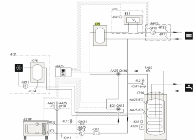
Looking at the below schematic, my system is I believe a similar setup to this, excluding CP6 and EB1 and any associated valves / pipework. CP5 is shown as the buffer vessel (which in my case is a Nibe UKV 20-40)
When looking at that installation manual for the UKV it doesn't actually show my configuration with the buffer, which I would say is different to the SMO20 installer manual screenshot?
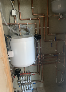
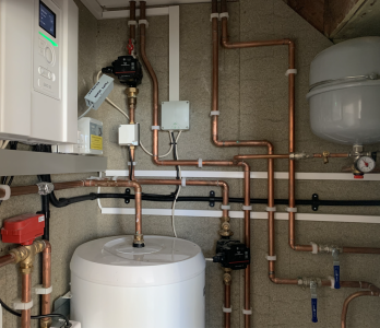
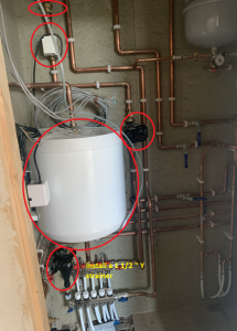
Here are a couple of pictures of my setup before it was finished and insulated.
@luke Your valve is fine, remove the items circled and you will have very good performance. You have plenty of system volume for the heat pump.
@heacol thanks for this. I will take these comments back to my installer.
May I ask why you would remove the TF1 filter for a strainer? Is this just to improve flow? Will there be other detrimental effects?
Also I presume you are saying that the system will run from just the charge pump as you are suggesting removal of both heating medium circulation pumps. (I like this idea as it will reduce base load, but I expect my installer will be hesitant to recommend this considering he installed both!)
@luke TF1 filter for a strainer? Is this just to improve flow? Will there be other detrimental effects? just to improve flow and stop parasitic losses. It will have no detrimental effect. It can be put back in parallel with the strainer if you are worried.
The installer will probably balk at removing them, but you are the customer.
- 27 Forums
- 2,495 Topics
- 57.8 K Posts
- 352 Online
- 6,220 Members
Join Us!
Worth Watching
Latest Posts
-
RE: What determines the SOC of a battery?
@batpred I didn't write the Seplos BMS software, I a...
By Bash , 11 minutes ago
-

RE: Electricity price predictions
Sorry to derail this thread ‘slightly?’ but back to the...
By Toodles , 20 minutes ago
-

RE: Humidity, or lack thereof... is my heat pump making rooms drier?
Without knowing it, @andrewj, you've laid down the gaun...
By Majordennisbloodnok , 39 minutes ago
-
RE: Testing new controls/monitoring for Midea Clone ASHP
@tasos and @cathoderay thanks. I have some history grap...
By benson , 43 minutes ago
-

I am having my existing heat pump changed to a Vaillant...
By trebor12345 , 1 hour ago
-
Our Experience installing a heat pump into a Grade 2 Listed stone house
First want to thank everybody who has contributed to th...
By Travellingwave , 2 hours ago
-
RE: Setback savings - fact or fiction?
@cathoderay The input power is largely determined by...
By RobS , 2 hours ago
-

RE: Solis inverters S6-EH1P: pros and cons and battery options
Just to wrap this up here for future readers: The S...
By Batpred , 4 hours ago
-
RE: Struggling to get CoP above 3 with 6 kw Ecodan ASHP
Welcome to the forums.I assume that you're getting the ...
By Sheriff Fatman , 4 hours ago
-
RE: Say hello and introduce yourself
@editor @kev1964-irl This discussion might be best had ...
By GC61 , 6 hours ago
-

@painter26 — as @jamespa says, it's for filling and re-...
By cathodeRay , 10 hours ago
-

RE: Oversized 10.5kW Grant Aerona Heat Pump on Microbore Pipes and Undersized Rads
@uknick TBH if I were taking the floor up ...
By JamesPa , 20 hours ago
-

RE: Getting ready for export with a BESS
I would have not got it if it was that tight
By Batpred , 22 hours ago
-
RE: Need help maximising COP of 3.5kW Valiant Aerotherm heat pump
@judith thanks Judith. Confirmation appreciated. The ...
By DavidB , 1 day ago
-

RE: Recommended home battery inverters + regulatory matters - help requested
That makes sense. I thought better to comment in this t...
By Batpred , 1 day ago
-
Bosch CS5800i 7kW replacing Greenstar Junior 28i
My heat pump journey began a couple of years ago when I...
By Slartibartfast , 1 day ago
-

RE: How to control DHW with Honeywell EvoHome on Trianco ActiveAir 5 kW ASHP
The last photo is defrost for sure (or cooling, but pre...
By JamesPa , 1 day ago
-

RE: Plug and play solar. Thoughts?
Essentially, this just needed legislation. In Germany t...
By Batpred , 1 day ago
-
RE: A Smarter Smart Controller from Homely?
@toodles Intentional opening of any warranty “can of wo...
By Papahuhu , 1 day ago
-
RE: Safety update; RCBOs supplying inverters or storage batteries
Thanks @transparent Thankyou for your advic...
By Bash , 1 day ago
-
RE: Air source heat pump roll call – what heat pump brand and model do you have?
Forum Handle: Odd_LionManufacturer: SamsungModel: Samsu...
By Odd_Lion , 1 day ago
-
RE: Configuring third party dongle for Ecodan local control
Well, it was mentioned before in the early pos...
By F1p , 2 days ago
-

RE: DIY solar upgrade - Considering adding more panels
I know this is a bit old, but it made me wonder what co...
By Batpred , 2 days ago

