Is this a bad installation and is there something wrong with my Samsung heat pump?
@editor it will be back to my installer to make that decision and if they can’t effect a repair then I will be expecting them to instruct the guys I’m getting out and foot the bill. There is a 12 months installation guarantee so legally I have them on that. Make enough noise and either they sort it or the folk like samsung distance themselves from the bad publicity. And they go bust as in the past. Local authority work alone going bottoms up is enough to sink them.
its a big market but and it’s a huge but, government incentives need to be productive to succeed and not dragged down by cowboy installers. Look at the ferry mess, they don't need hundreds of folk raising poor installation claims.
if you had a xxxx installed by xxxxx in 2024 and this has happened then call this number. I honestly see it coming.
Posted by: @david999said they only have to bond water or gas into house and with plastic it’s safe. Aside from the fact plastic is safe there are runs of copper and water is a conductor.
No one else has commented on this, so I think I'd better do so.
But please remember I'm not a qualified plumber or electrician.
The installer is slightly right, but not entirely so.
Imagine a house which is plumbed entirely with plastic piping.
The basin & sink taps will still be metal, but I don't think we'd expect each one to be individually earth-bonded.
My house is part copper and part plastic.
I did that work myself almost 20-years ago.
The metal parts I bonded were those which had mains-powered devices connected to them, but had plastic pipework between them and the cold water incomer.
That incomer would normally be called the 'rising main' but I have a well!
So the pump and its expansion vessel are earthed because the motor is!
Plastic pipe then takes the water elsewhere in the house, including two 50-litre tanks in the loft.
That's the fall-back we require in the event of a pump failure on a Friday afternoon.
(Yes, it has happened - twice. Once was just 6 weeks ago)
The main functional part of the water system is the thermal store.
It's copper, and has lots of copper pipework connected to it:
- boiler circuit
- UFH manifolds for two floors, with associated pump
- DHW cold input and hot output
- two showers (an en-suite backs onto the main bathroom)
- thermal-solar collector on roof, its pump and expansion vessel
All the 2-port valves, boiler and pumps are 240v AC, and have an earth wire running to them alongside live & neutral (Twin & ECC cable).
But if any of these needed repair/replacement, then there's a risk of an earth wire being disconnected whilst the work is carried out (by me!).
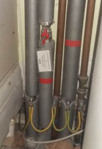
So there's a 10mm earth bond running across all the metal pipes around that thermal store.
Since the copper pipe runs were properly planned before I installed the thermal store, fixing the earth bond wire was straightforward:
Yes, all my valves are labelled in plain English.
Yes, all my pipe-runs are colour-coded.
How do I know that I've adequately placed earth-bonding where it's required?
... because when the Building Regs Surveyor looked into that corner behind the thermal store he said "I don't think anyone else would've bothered going to that extent".
There probably are regulations about the minutiae of when an earth bond is required on copper pipe within a house that has extensive runs in plastic.
But logic tells me that I don't need earth bonding where there's no mains-operated device which could make the pipe live.
So I wouldn't be putting an earth bond onto each radiator...
... unless it had an associated air-blower or a mains-operated valve connected to it.
I hope that approach makes sense.
Save energy... recycle electrons!
@transparent only thing is that the central sections of copper interlink with other areas like kitchen, so dish washer, washing machine, tumble dryer and sockets. Water solar on roof. Split consumer unit and a separate consumer unit for both heating and solar so we could not rely on an item such as a three port valve earthing to protect the pipes it would simply trip in its own consumer box or section. So in theory we could say the heating might be bonded through the components connected to the pipes but the house circuits are no longer protected because they broke the bond. Therefore if the dishwasher shorted it would not trip the main house breakers, and since the heating components are on a separate circuits would they even trip on their earth leakage since it measures voltage imbalance and it’s not the heating components live thats shorting so no imbalance. Bit rusty but I think I have it correct.
To conclude the bonding, if pipes are bonded the bonding goes back to the bonding bar and if any component or circuit shorts to those pipes then it chucks out an imbalance and shuts down the offending circuit. The earthing on pumps etc only protect that specific component and circuit.
Posted by: @david999The earthing on pumps etc only protect that specific component and circuit
I understand your point, but don't entirely agree.
If I inadvertently omitted an earth to an appliance, and a fault on that caused a water-pipe to 'go live', then the earth on a pump connected to the same system would be sufficient to cause the appliance's fuse/trip to blow.
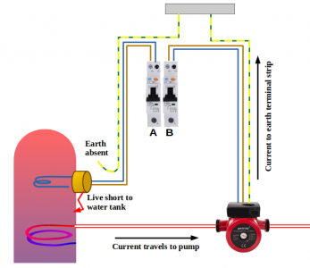
I've omitted switches and controllers in this diagram to aid clarity.
If a fault in the immersion heater causes the water cylinder to go live, the earth path back through the water pump should still be enough to cause Trip-A to open the contacts due to over-current.
Depending on the spec for trip-B it's possible that this will also open its contacts due to a presumed imbalance between phase & neutral.
It shouldn't make any difference whether trips A & B are at 'opposite ends' of a split-load consumer unit, or possibly even within different consumer units.
Earth is earth, whatever the location of the trips.
That tripping action occurs whether or not I've put an earth bond on the pipe between the cylinder and the pump.
The comment I received from my Building Regs inspector was because I had indeed put earth bonds on all pipes connected to my cylinder.
If, however, the pipe between the cylinder and the pump was plastic, then the fault current would have to travel through the water in order to cause trip-A to operate.
That's a higher-resistant path, and there would be greater delay before Trip_A operated due to over-current.
Within my own house I wouldn't be happy with that.
So all my power circuits are fed from independent RCBOs.
That means Trip-A will operate due to imbalance between live & neutral, rather than the fault current needing to return to the consumer unit via the pump.
Finally, within your kitchen, I agree that there is greater risk due to a number of appliances connected to different mains circuits and plumbing.
I would tend to add earth bonding to pipes in those circumstances.
What I'm unsure of is whether the regulations stipulate that it's required.
Save energy... recycle electrons!
@transparent now that’s a great explanation. I have been reading up on it and it’s a hard read, bonding and earthing both different, plastic and copper and a mix of copper and plastic connectors. Types of breakers, location of pipes and so on, and a section where bonding can increase risk of shock. So I’m going to opt for your ethos and connect mine back up, you thought it smart, a previous spark thought so as well, and before my head melts.
And this the great benefit of raising these issues in a discussion forum, of course. 🙂
Photos and diagrams help.
I happen to have a large library of shapes and icons available to use.
But a camera-phone snap of a diagram doodled on a back of envelope will do just as well.
I also happen to have a significant number of consumer units, containing a selection of different trips.
And I've learned a lot about the internal workings of trips through research what functionality is required to use them on DC (battery) supplies.
Chinese manufacturers are more than willing to state why their design is better than others!
Save energy... recycle electrons!
@transparent would you fit an isolator between your batteries and inverter, my installer refuses so I guess it’s down to me to fit one myself.
That's a good question @david999
to which I could've given an excellent response just a month ago.
However, there's a new Standard, PAS-63100-2024, sponsored by DESNZ and published by BSI.
Energy Storage Systems for Use in Buildings has been discussed here on this forum.
It's free to download, although it keeps referencing other earlier documents.
The Standard has mostly been written by Graham Kenyon, who is probably the most influential/senior member of the IET.
IET set the Code of Practice standards which apply to electrical installations in UK.
But this is the first time I've noticed them get involved in equipment working below 75v (known as Extra-low Voltage or ELV).
PAS-63100 concentrates on the risk of fire, rather than requirements to allow safe working on batteries and inverters which are already installed.
So it makes no mention of isolation switches for any of the equipment, which I find very odd!
It does insist [Sect 4.1.2] that any system which has 2 or more batteries in parallel should have a single 'over-current protection' device between those batteries and inverter(s).
Inverters are called PCE, for Power Conversion Equipment which doesn't help with clarity of the text. 😥
Since any storage battery will always be 'live' I can't see how you could safely maintain/repair a PCE unless there was an isolator present on the battery input.
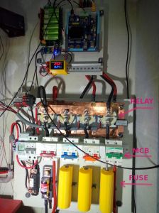
So I use two 'over-current protection' devices between each battery and the set of inverters (PCEs).
One of these is a fast-acting fuse, and the other is a double-pole MCB (rated 125A DC).
The latter has a lever which can be moved by hand, thus allowing it to be used as an isolator.
The photo also shows a 500A relay for each battery.
But I require those only because I have an overall smart controller for the battery storage system.
I would expect you to have a DC-rated MCB between your battery and inverter.
That's an over-current protection device which satisfies PAS-63100, and also provides the manual isolation you're seeking.
However... that MCB would operate far too slow to prevent an inverter catching fire due to an internal short-circuit.
Only a Type-T fuse could act fast enough to sever the battery connection, which could be delivering well over 1000A into the short-circuit location.
At such a high current, other 'protection' devices would simply arc across the contacts and weld them together!
... and that's a deficiency in the aims of PAS-63100.
What's the point of complying with this new standard if it allows appliances to be installed such that a fire still won't be prevented?
Stand by for a comment here from @kenbone
He and I have already found agreement in our views of regulations from MCS and RECC.
I need to add BSI/IET to my list of organisations whose regulations aren't helping professionals to achieve safe, functional and efficient installation.
Save energy... recycle electrons!
@transparent that’s mine straight from batteries to inverter.
what have you thought about fire, I thought about a fire blanket and a foam device. Mine are in the loft so thinking a firewall around all the gear.
My system installed last year in November in the loft so might have missed these regs
The PAS-63100:2024 Standard didn't exist last November.
Like most PAS standards, it isn't 'mandatory', nor retrospective.
However, now that it exists, there is a strong possibility of house insurers insisting on it being implemented.
That means existing sites would need to be certified by a qualified electrician... despite the fact that UK regulations do not require qualified electricians to be used for ELV installations.
I think that would set back the progress towards Net Zero by acting as a deterrent for domestic storage installation.
Scottish crofters have been doing this for decades, and I've never yet heard of their homes bursting into flames due to batteries catching fire!
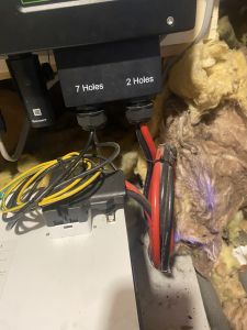
Coming back to the connection wires between your battery(ies?) and inverter, thanks for the photo.
Let's stick to common sense rather than delving too deep into the underlying physics!
In my opinion, any coil of wire is an inductor.
The higher the current, the greater is the magnetic field formed at right-angles to the plane of the coil.
Creating magnetic flux takes energy.
Conversion of energy from electricity to magnetism incurs losses, which will be manifested as heat.
It's possible that your installer was absent during that particular science lesson, of course.
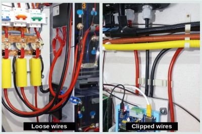
I think those (25mm² ?) wires should be set free from those nylon ties, and cut back to the required length.
A 25mm² wire is rated at 170A.
It is best either hung loose or clipped slightly apart from other wires in the system:
... and this is probably the best moment to consider how your wires can have a Type-T fuse and a breaker installed. 🤔
I'll comment on fire blankets etc separately.
But @editor might prefer that we relocate this conversation to a topic in the Energy Storage section!
Save energy... recycle electrons!
- 27 Forums
- 2,495 Topics
- 57.8 K Posts
- 260 Online
- 6,220 Members
Join Us!
Worth Watching
Latest Posts
-
RE: Setback savings - fact or fiction?
@cathoderay The input power is largely determined by...
By RobS , 10 minutes ago
-

RE: Humidity, or lack thereof... is my heat pump making rooms drier?
@editor, this is now an example of greenwashing in the ...
By Majordennisbloodnok , 21 minutes ago
-

RE: Electricity price predictions
@transparent Im impressed by all your work on this. ...
By JamesPa , 2 hours ago
-

RE: Solis inverters S6-EH1P: pros and cons and battery options
Just to wrap this up here for future readers: The S...
By Batpred , 2 hours ago
-
RE: Struggling to get CoP above 3 with 6 kw Ecodan ASHP
Welcome to the forums.I assume that you're getting the ...
By Sheriff Fatman , 2 hours ago
-

RE: What determines the SOC of a battery?
I agree. Fogstar confirmed that the Seplos BMS does ...
By Batpred , 3 hours ago
-
RE: Say hello and introduce yourself
@editor @kev1964-irl This discussion might be best had ...
By GC61 , 4 hours ago
-

RE: Testing new controls/monitoring for Midea Clone ASHP
@benson — as @tasos suggests, plotting multiple variabl...
By cathodeRay , 6 hours ago
-

@painter26 — as @jamespa says, it's for filling and re-...
By cathodeRay , 8 hours ago
-

RE: Oversized 10.5kW Grant Aerona Heat Pump on Microbore Pipes and Undersized Rads
@uknick TBH if I were taking the floor up ...
By JamesPa , 18 hours ago
-

RE: Getting ready for export with a BESS
I would have not got it if it was that tight
By Batpred , 20 hours ago
-
RE: Need help maximising COP of 3.5kW Valiant Aerotherm heat pump
@judith thanks Judith. Confirmation appreciated. The ...
By DavidB , 23 hours ago
-

RE: Recommended home battery inverters + regulatory matters - help requested
That makes sense. I thought better to comment in this t...
By Batpred , 24 hours ago
-
Bosch CS5800i 7kW replacing Greenstar Junior 28i
My heat pump journey began a couple of years ago when I...
By Slartibartfast , 24 hours ago
-

RE: How to control DHW with Honeywell EvoHome on Trianco ActiveAir 5 kW ASHP
The last photo is defrost for sure (or cooling, but pre...
By JamesPa , 1 day ago
-

RE: Plug and play solar. Thoughts?
Essentially, this just needed legislation. In Germany t...
By Batpred , 1 day ago
-
RE: A Smarter Smart Controller from Homely?
@toodles Intentional opening of any warranty “can of wo...
By Papahuhu , 1 day ago
-
RE: Safety update; RCBOs supplying inverters or storage batteries
Thanks @transparent Thankyou for your advic...
By Bash , 1 day ago
-
RE: Air source heat pump roll call – what heat pump brand and model do you have?
Forum Handle: Odd_LionManufacturer: SamsungModel: Samsu...
By Odd_Lion , 1 day ago
-
RE: Configuring third party dongle for Ecodan local control
Well, it was mentioned before in the early pos...
By F1p , 2 days ago
-

RE: DIY solar upgrade - Considering adding more panels
I know this is a bit old, but it made me wonder what co...
By Batpred , 2 days ago
-

RE: New Vaillant aroTherm Plus in black - When will it come to the UK?
@majordennisbloodnok Daikin, take note! (In fact, I hav...
By Toodles , 2 days ago
-

RE: Midea ASHP – how to set weather compensation
@mk4 — good work! First, I agree, no evidence of cycl...
By cathodeRay , 2 days ago

