My experience with the Selpos Mason DIY kit
Posted by: @transparentexport to the grid!
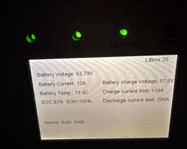
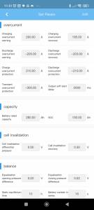
Sorry, I rather hurriedly wrote that reply. Yes, battery discharge current. And I included the wrong photo for the Lithium BMS page.
Posted by: @transparentupgraded where?
Upgraded within the master BMS. I actually set 110A charge/discharge limits on each BMS individually, but this seems to have been converted (min(2 *110A, 200A)???) into 200A. I think that when I tried to connect to the Seplos BMS through Bluetooth when operating in master/slave mode I could get connected.
Well @chickenbig - it seems that you're experiencing similar issues with BMS units in parallel, to those I've found with Growatt inverters in parallel.
When settings are changed on a Master device, some of those get replicated or modified when being replicated to slave units.
And other parameters don't get passed to slave units at all!
Inverter manufacturers are too quick in releasing code which allows them to declare 'compatibility' with BMS units.
BMS manufacturers might be equally at fault.
If these parameters were associated with export to the grid, then they wouldn't pass ENA checks and revised code would be re-submitted for test.
That failure effects the potential sales.
Because off-grid operations aren't covered by safety regulations, we're left sorting through a mish-mash of partially-tested features.
I don't like any operation which automatically adjust a current-limit UPWARDS !
A: What happens if one of those two Seplos BMS units takes its battery offline (for all the right reasons)?
With no current-sharing now in operation, does the other unit take all 200A?
Or do the BMS units notify each other and reduce the current limit automatically?
B: What happens if one of the two Seplos BMS units fails (for all the wrong reasons!)?
How could it communicate this to the other 'live' BMS in order to reduce the current?
I really don't like having communications links (CANbus or RS485) between units.
We're relying on unspecified actions occurring on devices which we have implemented for safety.
That's not safe !
Save energy... recycle electrons!
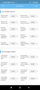
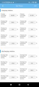
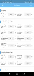
I still don't see an option on Seplos for setting Charge/Discharge current on Bluetooth BMS settings. I'll try to get desktop PC Battery Monitor setup and
see what
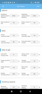
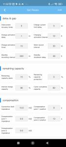
I can find. Here are Bluetooth BMS options, for reference.
To clarify, hopefully, these are the options for setting charge/discharge rates on a Sunsynk and single Seplos setup.
Charge Rate
- BMS Charge Limit - example 100A charge rate on Seplos Mason, the BMS can control this rate down though (based on? Temp, over voltage?)
- Batt Charge page - example, 60A. The inverter will use this value to charge the battery at 60A, even if BMS allows 100A. If BMS restricts to 40A for example, then inverter will charge at this instead.
- Batt Type page - example 100A. This is the global value, it will be ignored in the case of both Batt Charge setting and BMS Charge limit is less than this.
Discharge Rate
- BMS Discharge Limit - example 195A charge rate on Seplos Mason, the BMS can control this rate down though (based on? Temp, over voltage?)
- Batt Type page - example 100A. This is the global value, it will be ignored in the case of both Batt Charge setting and BMS Discharge limit is less than this.
- Inverter power Limiter setting - example 5000W. As @chickenbig mention in a post, if this power is limited (for example to bring under 3.68kW then presumably the inverter will also restrict the battery discharge power.
- Inverter power on System 1 page - example 5000W. Not sure where this fits in - could be it overrides all the others if lower.
Could be tidied up by Sunsynk!
Assuming two battery setup advertises 2 x 100A charge limit to inverter, although what happens if one BMS wants only 40A and the other wants 100A, is the inverter still trying to charge at 200A?
I'm assuming that at the inverter we can always restrict the current drawn by various settings ("Battery type" Charge/Discharge Amps, "Battery Charge" Grid Charge Amps, "System Mode 1" charge power, "Li BMS" diagnostic page Charge/discharge current limit). Greater visibility into the inverter decision-making would certainly help with building confidence.
Posted by: @transparentA: What happens if one of those two Seplos BMS units takes its battery offline (for all the right reasons)?
With no current-sharing now in operation, does the other unit take all 200A?
Or do the BMS units notify each other and reduce the current limit automatically?B: What happens if one of the two Seplos BMS units fails (for all the wrong reasons!)?
How could it communicate this to the other 'live' BMS in order to reduce the current?
The inverter, battery BMS and fuse form (somewhat) independent protection systems, although adding communication between the BMSs and also the inverter couples things somewhat. Personally I would not want to add more complexity by having a battery bus monitor (checking fuse status, monitor current flow per battery etc) and have that monitor take action (e.g. activate a shunt trip coil).
The system was specced to stay within component limits (inverter has maximum current draw of 120A, all fuses are 125A, fuse holder is rated to 160A, BMS is 200A, 25mm2 wires from inverter to main fuse (so 170A limit), 50mm2 wire from battery to per-battery fuses (so 345A limit)). Much like keeping our grade B cells well away from the high charge/discharge rates they were intended (but rejected) for, we can keep things away from the point at which complexity snowballs!
Posted by: @vaugi- Inverter power Limiter setting - example 5000W. As @chickenbig mention in a post, if this power is limited (for example to bring under 3.68kW then presumably the inverter will also restrict the battery discharge power.
I think the "System Mode 2" "Export power limiter" setting limits just what is exported onto the grid after house usage is subtracted i.e. with a 3680W limit I could take 5000W (well more like 5200W after conversion losses) out of the battery provided the house load is >= 1320W.
Posted by: @vaugiCould be tidied up by Sunsynk!
It seems similar to the Seplos BMS translation; could be much better but given the state of things I guess feedback is not so readily actioned.
Posted by: @chickenbigGreater visibility into the inverter decision-making would certainly help with building confidence.
Yes. That's where we're in agreement.
Simply having the units talking to each other isn't reassuring me that they'll arrive a sensible answers - especially if there's fault.
Posted by: @chickenbigPersonally I would not want to add more complexity by having a battery bus monitor (checking fuse status, monitor current flow per battery etc) and have that monitor take action (e.g. activate a shunt trip coil).
I'm looking into this using a properly-engineered, well-designed approach.
FWIW I'm currently running a battery without a BMS.
It has an active balancer, but the other three functions are being handled by my own electronics and software.
That's why you can see whopping big relays/solonoids in some of the photos I've posted! 😮
Save energy... recycle electrons!
Thanks, I have had my Sofar uninstalled and am going to go through the full DNO process, as you suggested with EV charger, 28.6kw of batteries, 5kw Sunsynk, so that i only make one application for everything (although i assume octopus will take care of the EV 'bit' as i am looking for them to install one of their OHME chargers.
i am now able to switch my tariff to Intelligent Octopus as my current deal has ended. i dont have an EV though 'yet' but i am happy to have the OHME car charger installed as we often let out our home as an Air BnB and its something people have enquired about.
in your opinion, would i still be able to also utilise the 6 hour period for my storage heaters? my setup is a little different in that we have a three phase supply, but only use two phases. one phase for general household use, the other phase only becomes live during off peak periods, controlled by the smart meter.
during the off peak periods, general household use 'power' is charged at off peak rates, so everything goes through the smart meter, so would it matter which phase the EV charger was connected to ? though i suspect the installers would work all that out for me ...
Posted by: @misterbwe have a three phase supply, but only use two phases
From a grid perspective I would think that using all three phases equally would be the best, especially when adding large loads like an EV charger and inverter. Turning on one phase during off-peak hours strikes me as a bit of a bodge to avoid running control lines to the storage heaters, although nowadays there is probably the possibility of a wireless connection to the smart meter.
its always been like that, the house was built in 1950 and storage heaters added i assume in the 60/70's. i replaced them all two years ago with dimplex quantums, so they are all pretty efficient and all now have feeds both from the overnight supply (one phase) and the untimed general house supply (to power the boost settings)
im not really looking to alter that set up as it works as it is for us.
- 27 Forums
- 2,495 Topics
- 57.8 K Posts
- 228 Online
- 6,220 Members
Join Us!
Worth Watching
Latest Posts
-

RE: Humidity, or lack thereof... is my heat pump making rooms drier?
@majordennisbloodnokjordennisbloodnok, this is in an in...
By Mars , 2 minutes ago
-

RE: Electricity price predictions
@transparent Triggered by the various commen...
By JamesPa , 45 minutes ago
-

RE: Solis inverters S6-EH1P: pros and cons and battery options
Just to wrap this up here for future readers: The S...
By Batpred , 1 hour ago
-
RE: Struggling to get CoP above 3 with 6 kw Ecodan ASHP
Welcome to the forums.I assume that you're getting the ...
By Sheriff Fatman , 1 hour ago
-

RE: What determines the SOC of a battery?
I agree. Fogstar confirmed that the Seplos BMS does ...
By Batpred , 2 hours ago
-
RE: Say hello and introduce yourself
@editor @kev1964-irl This discussion might be best had ...
By GC61 , 3 hours ago
-

RE: Testing new controls/monitoring for Midea Clone ASHP
@benson — as @tasos suggests, plotting multiple variabl...
By cathodeRay , 5 hours ago
-

@painter26 — as @jamespa says, it's for filling and re-...
By cathodeRay , 7 hours ago
-

RE: Oversized 10.5kW Grant Aerona Heat Pump on Microbore Pipes and Undersized Rads
@uknick TBH if I were taking the floor up ...
By JamesPa , 17 hours ago
-

RE: Getting ready for export with a BESS
I would have not got it if it was that tight
By Batpred , 19 hours ago
-

RE: Setback savings - fact or fiction?
I also need to correct something I said by mistake earl...
By cathodeRay , 19 hours ago
-
RE: Need help maximising COP of 3.5kW Valiant Aerotherm heat pump
@judith thanks Judith. Confirmation appreciated. The ...
By DavidB , 22 hours ago
-

RE: Recommended home battery inverters + regulatory matters - help requested
That makes sense. I thought better to comment in this t...
By Batpred , 23 hours ago
-
Bosch CS5800i 7kW replacing Greenstar Junior 28i
My heat pump journey began a couple of years ago when I...
By Slartibartfast , 23 hours ago
-

RE: How to control DHW with Honeywell EvoHome on Trianco ActiveAir 5 kW ASHP
The last photo is defrost for sure (or cooling, but pre...
By JamesPa , 1 day ago
-

RE: Plug and play solar. Thoughts?
Essentially, this just needed legislation. In Germany t...
By Batpred , 1 day ago
-
RE: A Smarter Smart Controller from Homely?
@toodles Intentional opening of any warranty “can of wo...
By Papahuhu , 1 day ago
-
RE: Safety update; RCBOs supplying inverters or storage batteries
Thanks @transparent Thankyou for your advic...
By Bash , 1 day ago
-
RE: Air source heat pump roll call – what heat pump brand and model do you have?
Forum Handle: Odd_LionManufacturer: SamsungModel: Samsu...
By Odd_Lion , 1 day ago
-
RE: Configuring third party dongle for Ecodan local control
Well, it was mentioned before in the early pos...
By F1p , 2 days ago
-

RE: DIY solar upgrade - Considering adding more panels
I know this is a bit old, but it made me wonder what co...
By Batpred , 2 days ago
-

RE: New Vaillant aroTherm Plus in black - When will it come to the UK?
@majordennisbloodnok Daikin, take note! (In fact, I hav...
By Toodles , 2 days ago
-

RE: Midea ASHP – how to set weather compensation
@mk4 — good work! First, I agree, no evidence of cycl...
By cathodeRay , 2 days ago

