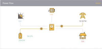
Posted by: @chickenbigAt the risk of stating the obvious (or even non-obvious), suggests that you need to set the microinverter check-box ("For micro inverter input"?) on the Aux page even if you are AC coupling (i.e. not putting the inverter on the Aux AC connection).
I love you @chickenbig 😍 Works lovely now, I've seen that video before, but not while I was trying to fix this issue. Totally not obvious, to me anyway, and shows that we should not have to be trying to hunt this information down in disparate vidoes! Although to give Sunsynk credit, presumably their approved installers know most of this...problem comes down to us "advanced users" who also want to know how to change setups for future use cases.
Just need to work out the BATT OFF 100% and BATT ON 95% Micro-inverter settings to understand what it means, just testing that now.
So in relation to this thread - and @misterB - these Sunsynk do work nicely as AC-coupled as he intends.
Posted by: @vaugiPosted by: @chickenbigAt the risk of stating the obvious (or even non-obvious), suggests that you need to set the microinverter check-box ("For micro inverter input"?) on the Aux page even if you are AC coupling (i.e. not putting the inverter on the Aux AC connection).
I love you @chickenbig 😍 Works lovely now, I've seen that video before, but not while I was trying to fix this issue. Totally not obvious, to me anyway, and shows that we should not have to be trying to hunt this information down in disparate vidoes! Although to give Sunsynk credit, presumably their approved installers know most of this...problem comes down to us "advanced users" who also want to know how to change setups for future use cases.
Just need to work out the BATT OFF 100% and BATT ON 95% Micro-inverter settings to understand what it means, just testing that now.
-- Attachment is not available --
So in relation to this thread - and @misterB - these Sunsynk do work nicely as AC-coupled as he intends.
thanks for the confirmation
are you happy to share your g99 application with me, i need my hand holding as i go through it - much easier to copy and adapt the application someone else has already had approved??
Posted by: @vaugiTotally not obvious, to me anyway, and shows that we should not have to be trying to hunt this information down in disparate vidoes!
Hopefully Google indexing will mean that this problem and solution can be solved more easily in the future. I presume Sunsynk (or Deye) are reluctant to add more settings pages, so have shoe-horned AC coupled inverters into the Aux page, similar to the setting of inverter shutdown voltages (in addition shutdown SoC) which needs to be set when the battery type selected is "AGM V".
Project update
After spending a couple or months on holiday around Europe (Static van in France (now sold) and then touring in our motorhome)
i finally got round to having my Sofar ME3000SP removed and the Sunsynk 5.5Kw ECCO installed following G99 approval, all working well. I even managed to set up the micro inverter/AC coupled settings, so thanks to everyone who shared their knowledge, especially @ChickenBig
one issue that did arise though, in case anyone else has the same concerns, was the use of the comms cable, the sunsynk manual states that the cable is marked specifically for connecting each end to either the battery or the inverter. my sunsynk came with a yellow cable and no labels to identify which end goes where .... i neednt have worried, i just plugged one end into the inverter and the other end into the battery and it worked! i assume they have 'designed' the cable orientation issue out, so it no longer matters.
@vaugi - did you get round to working out that the settings mean? i took them to mean that when the battery is at 100% then the power input via the AC couple inverter would stop and then restart when the battery dropped down to 95%? i assume to stop it constantly 'kicking in and out'?
just surprised that Sunsynk havent produced a short video showing how to do it. i did watch the two youtube videos posted earlier in the thread, but it could be explained a lot simpler in all honesty. there are prob thousands of existing PV systems, installed under the FiT scheme that would benefit from the addition of home storage batteries, so perhaps theyre missing expanding their market?
I am visiting the solar and storage show at the NEC this week, so i will stop by their stand and 'suggest' it and see if they have any info i need to be aware of.
Posted by: @misterbi took them to mean that when the battery is at 100% then the power input via the AC couple inverter would stop and then restart when the battery dropped down to 95%?
That was also my interpretation.
But it doesn't seem to me a feature likely to be used by those reading this Forum.
Keeping a battery topped-up is usually associated with a mission-critical requirement.
You find this approach used in operating theatres and server-rooms for example.
Most battery chemistries suffer greater degradation (shorter lifetime) if you keep them at near-full capacity.
Here on this Forum we're more likely to have members who have a Time-of-Use tariff (from Octopus) and some amount of solar input.
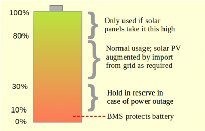
We will probably operate our batteries between 30% to 80% full.
That will depend on the amount of solar we expect to have available the next day, and the cost-per-kWh offered from our chosen tariff each half-hour.
I was a delegate at an energy seminar last week where I met someone who was indeed needing to install a large number of batteries which would be maintained at a high level of charge.
They would still be used on a daily basis to some extent, but must be available in the event of a grid-outage lasting more than 10-hours or so.
That's a tricky problem to solve.... and results in a massive capital expense which sits idle for several years waiting for the apocalypse to arrive.
It's possible that our present range of battery chemistries are not best suited for the task.
Save energy... recycle electrons!
Posted by: @misterbi finally got round to having my Sofar ME3000SP removed and the Sunsynk 5.5Kw ECCO installed following G99 approval, all working well
\o/ That's great news; I'm glad you've got things sorted out and that this serves as a good example of how to evolve a PV system. I hope that Sunsynk are willing to take onboard your feedback and make things clearer to consumers and installers ... better documentation can work wonders for sales.
Posted by: @transparentI met someone who was indeed needing to install a large number of batteries which would be maintained at a high level of charge.
They would still be used on a daily basis to some extent, but must be available in the event of a grid-outage lasting more than 10-hours or so.
There looks to be a mismatch between charge/discharge rate and capacity. LiFePO4 batteries can have C-rates of about 0.5 (i.e. 2 hours to charge/discharge). I would hope that such a mismatch would get segmented to generate revenue ... at sufficient scale it might be possible to sell off 10% of capacity and >> 10% of the charge/discharge power for arbitrage as a virtual power plant.
This vid (off grid garage) talks about cell compression versus life. In a nutshell: you cannot stop cells expanding a mm or so when full- 300kg (3kN force) will not prevent that. However during the first few charges, a few trapped air bubbles are released - compression channels these away rather than causing damaging delamination. Cells could expand more due to this trapped air. He does also point out that age will generally deteriorate these cells well before cycling, so it’s not that much of a concern to him.
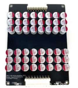
I have just got a delivery of EVE304k cells and a lovely vertical Seplos mason box from fogstar. Thanks you to all on this forum that have shown the way! It’s currently top balancing unconventionally in a series string- I put all cells as normal in the Seplos box, compressed them, and connected normally, with the weak Seplos bms. I then added an additional much more powerful active bms(a capacitive balancer, moves caps from cell to cell) to keep the cell voltages close as the pack slowly charges up to full - charging at 2A while the active balancer can move up to 5A. When it’s full and well matched (every cell at 3.55V +-3mV) I’ll remove the active balancer, that will leave the weaker Seplos one in place.
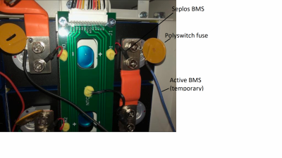
All the extra active balance cables have inline fuses as I’m appropriately nervous with those cells. If something went wrong, the Seplos bms should disconnect the 2A psu, or a fuse should blow.
This will all be connected to a Sunsynk hybrid inverter, via some chunky cable and a DC breaker.
Interesting points you're making @robl
There is probably little harm in doing things unconventionally... especially when in discussion with others on this Forum.
It's possible that issues like compression (or not) will affect charge retention in years to come, but us experimenters probably aren't installing adequately accurate monitoring (or any experimental control) to know if that's true.
The last batch of EVE cells which I imported (direct from China) were labelled 280Ah, but their true capacity was around 300Ah. I'm unsurprised at this.
Firstly EVE will be gradually improving the manufacturing process to minimise flaws in the chemical deposits on the electrodes.
Secondly all reputable manufacturers will quote the lowest capacity figure that they are confident in delivering to a customer. The one thing they want to avoid is a cell that falls short of its specification. Not only would that fall foul of the Consumer Rights Act, but also risks damage to their reputation.
I think the 304Ah cell is basically the same product, but with a greater level of confidence from EVE!
They can still sell the ones which don't pass the capacity test as a 280Ah product.
I've also been offered a 560Ah cell from EVE.
But it's physically twice the size, and thus the same energy density.
I'm also interested to see @robl using an active balancer in parallel with the Seplos BMS.
Their BMS is a passive balancing system.
It burns off energy from the cell with the highest voltage by passing it through a resistor.
Adding the active balancer will ensure that the BMS burns away a continuous stream of energy... and will presumably get quite warm!
I too use fuses on all balance leads, but I'm only balancing at 2A (with a 3A fuse).
The 'standard' in-line fuseholders for 20x5mm cartridge fuses are most often provided with pre-attached wire of 16/0.2 construction.
Depending on the manufacturer, that will have a maximum current rating of 3A or 4A.
So I'd really like to hear more from Rob about the fuses and holders he's using for an active balancer rated at 5A.
Photo please?
Save energy... recycle electrons!
Posted by: @roblAll the extra active balance cables have inline fuses as I’m appropriately nervous with those cells. If something went wrong, the Seplos bms should disconnect the 2A psu, or a fuse should blow.
How does one ensure that the resistance of fuses do not adversely affect the voltage measurement? There are 4 additional junctions as well as a fuse. Will these fuses be sufficient to break a fault current?
As an aside, it does seem as if the active balancers are somewhat liable to stop working (see the Will Prowse video where one combusted, and Stuart Pittaway did a tear-down after his balancer broke). That is, additional safety measures may be warranted if leaving the balancer permanently attached. Perhaps this is a reason to perform balancing once a year; attach a NEEY 15A balancer, be done in 1/2 an hour and leave the system with fewer components!
Posted by: @chickenbigHow does one ensure that the resistance of fuses do not adversely affect the voltage measurement?
The active balancer is only measuring differential voltage. Since each wire has approximately the same resistance added to it by the fuseholder, the voltage differences aren't affected.
But it's a valid question.
I had a problem when adding fuseholders on one occasion.
The crimp-tool I was using wasn't well-suited to the design of M6 brass ring-terminals for the cell-connection end.
That resulted in poor connections with increased resistance.
The solution was to cut off all the terminals and re-do the operation with a different (new) pair of crimp pliers.
I now have five crimp pliers in my arsenal, and a better understanding of which size and style of crimp jaws are required for each type of connector. 🙂
My smallest crimp tool was proportionally by far the most expensive.
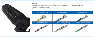
Several years ago I paid £50 for a PA-20 made by Precision in Japan. It's excellent for the tiny crimp terminals used inside PCB connectors.
The Precision Engineer range of crimp tools is now available from several UK suppliers at lower cost.
Save energy... recycle electrons!
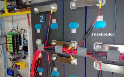
Piccy as requested, a pic of a few cells showing active balancer attached with fuses. The fuses are actually 3.75A 75V self resetting "polyswitch" PTC "fuses" - as the current through them goes beyond around 4A, they heat up and increase in resistance, and quickly become high impedance. They never go fully open circuit - but they're fine to prevent a cable melting disasterously. I think in retrospect a regular fuse in a socket would be better - I would've appreciated to be able to fit them one at a time to enable the active BMS after complete assembly. Note that this extra stage is only for initial charging - in a few days the cells will be full, and I'll remove these extra cables, fully tighten the bolts, run it all as Seplos intend.
The extra BMS is not lossy, it does not get hot - it's a capacitive switch mode device. It uses lots of Mosfets to switch capacitors from one cell to another. If they are the same voltage, no current flows in/out of the cap. If one is higher, then every move transfers some charge. This repeats - guestimate at a kHz or so - so long as the cell voltages are over 3V. A pic below of the balancer we got:
@ChickenBig: The polyswitch fuses do affect the active balancer - they make it higher impedance, so a bit worse. I did a "4 terminal" resistance measurement on one of them - pushed 1A through a fuse and measured the voltage drop directly on the fuse wires with a multimeter. This measured 38mV, so the polyswitch resistance when cold is 38mOhms. The balancer says it will push 1A into a cell that is 100mV lower than the rest - ie. 100mOhms, pulling a bit of current from each of the other cells. So my adding the fuses makes the balancer that bit worse, at 138mOhms.
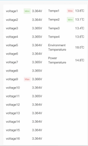
The way I see it, is that if I charge the whole string at 2A, then the balancer will keep every cell within 2*.138V = 0.276V of the mean.
I'm checking progress regularly - find the peak cell voltage as indicated by Seplos bms (pic). Find 3.65V- whatever that is. Set my 60V 2A bench supply to that much over the present pack voltage. So presently the bench supply says constand current 2A @54.07V - and I've put it's voltage target as 54.3V. Cautious like. At 2A, the pack should take less than 304Ah/2A = 152 hours to charge.
No, it's the existing Seplos BMS which will be getting warm.
It should be burning off the extra voltage through its resistors.
The whole point of a passive balancing system is to convert the electrical energy into heat.
Personally I wouldn't use a Polyfuse in such an application.
The 3.75A and 75v max rating suggest to me that you're using Tyco/Raychem units, rather than Littelfuse, who are the market leaders.
Littelfuse's range are rated at 60v or 72v max operating voltage.
But you're also using them beyond the trip-point.
The resistance they offer to the circuit is extremely variable in such a configuration.
The Active Balancer won't be effective because there is too much variation from one cell to another.
I can't think of a fault condition you're likely to encounter where a Polyfuse could offer adequate protection.
It's a temperature-based device. So it needs to heat up sufficiently to make its resistance increase and shut-off the current flow.
It's far too slow for what you want.
Posted by: @roblIf one is higher, then every move transfers some charge. This repeats - guestimate at a kHz or so
Erm... no.
Active balancers don't operate at the kilohertz range.
Their micro-controller takes time to measure the cell voltages and decide which is the highest and lowest in the set.
To do so it first switches off the current flow on all balance leads.
So I doubt it will be switching between one cell and another faster than 10 times per second!
Save energy... recycle electrons!
- 27 Forums
- 2,495 Topics
- 57.8 K Posts
- 227 Online
- 6,220 Members
Join Us!
Worth Watching
Latest Posts
-

RE: Humidity, or lack thereof... is my heat pump making rooms drier?
@majordennisbloodnokjordennisbloodnok, this is in an in...
By Mars , 4 minutes ago
-

RE: Electricity price predictions
@transparent Triggered by the various commen...
By JamesPa , 47 minutes ago
-

RE: Solis inverters S6-EH1P: pros and cons and battery options
Just to wrap this up here for future readers: The S...
By Batpred , 1 hour ago
-
RE: Struggling to get CoP above 3 with 6 kw Ecodan ASHP
Welcome to the forums.I assume that you're getting the ...
By Sheriff Fatman , 1 hour ago
-

RE: What determines the SOC of a battery?
I agree. Fogstar confirmed that the Seplos BMS does ...
By Batpred , 2 hours ago
-
RE: Say hello and introduce yourself
@editor @kev1964-irl This discussion might be best had ...
By GC61 , 3 hours ago
-

RE: Testing new controls/monitoring for Midea Clone ASHP
@benson — as @tasos suggests, plotting multiple variabl...
By cathodeRay , 5 hours ago
-

@painter26 — as @jamespa says, it's for filling and re-...
By cathodeRay , 7 hours ago
-

RE: Oversized 10.5kW Grant Aerona Heat Pump on Microbore Pipes and Undersized Rads
@uknick TBH if I were taking the floor up ...
By JamesPa , 17 hours ago
-

RE: Getting ready for export with a BESS
I would have not got it if it was that tight
By Batpred , 19 hours ago
-

RE: Setback savings - fact or fiction?
I also need to correct something I said by mistake earl...
By cathodeRay , 19 hours ago
-
RE: Need help maximising COP of 3.5kW Valiant Aerotherm heat pump
@judith thanks Judith. Confirmation appreciated. The ...
By DavidB , 22 hours ago
-

RE: Recommended home battery inverters + regulatory matters - help requested
That makes sense. I thought better to comment in this t...
By Batpred , 23 hours ago
-
Bosch CS5800i 7kW replacing Greenstar Junior 28i
My heat pump journey began a couple of years ago when I...
By Slartibartfast , 23 hours ago
-

RE: How to control DHW with Honeywell EvoHome on Trianco ActiveAir 5 kW ASHP
The last photo is defrost for sure (or cooling, but pre...
By JamesPa , 1 day ago
-

RE: Plug and play solar. Thoughts?
Essentially, this just needed legislation. In Germany t...
By Batpred , 1 day ago
-
RE: A Smarter Smart Controller from Homely?
@toodles Intentional opening of any warranty “can of wo...
By Papahuhu , 1 day ago
-
RE: Safety update; RCBOs supplying inverters or storage batteries
Thanks @transparent Thankyou for your advic...
By Bash , 1 day ago
-
RE: Air source heat pump roll call – what heat pump brand and model do you have?
Forum Handle: Odd_LionManufacturer: SamsungModel: Samsu...
By Odd_Lion , 1 day ago
-
RE: Configuring third party dongle for Ecodan local control
Well, it was mentioned before in the early pos...
By F1p , 2 days ago
-

RE: DIY solar upgrade - Considering adding more panels
I know this is a bit old, but it made me wonder what co...
By Batpred , 2 days ago
-

RE: New Vaillant aroTherm Plus in black - When will it come to the UK?
@majordennisbloodnok Daikin, take note! (In fact, I hav...
By Toodles , 2 days ago
-

RE: Midea ASHP – how to set weather compensation
@mk4 — good work! First, I agree, no evidence of cycl...
By cathodeRay , 2 days ago

