Real world connection to a heat pump over modbus
@cathoderay thanks - I won't hold out too much hope on the FHP option then.
Posted by: @ctw
- Is there any guidance out there on how to actually wire up the Midea controller? I did find this YouTube video which appears to show how to do this - is someone able to confirm this is correct, and not somethign specific to Homely?
- I've done some searching through all the documentation I have to hand, but don't appear to have anything that contains the modbus register, which I’ve seen referenced. Does anyone know where there is a copy of this online.
On my GitHub page you will find info about the connection and modbus registers.
https://github.com/Mosibi/Midea-heat-pump-ESPHome
@mosibi - thanks for your contribution, looks like an interesting project! However, it does tie the user to using your hardware, ESPHome and Home Assistant, and not everyone (I for one) wants to be tied to Home Assistant.
I note that you have most if not all of the modbus register addresses in your heatpump.yaml file, starting at line 319.
For historical reasons, I do have HA installed (the historical reason being I started out intending to use HA, and then decided otherwise) and by having HA installed, I also have a small Linux OS on the mini computer which I use to run the python scripts that do my monitoring and DIY auto-adaption control. The physical connection is a wired connection that has a RS485 to USB adadapter at the mini computer end, and the viewing of data and management of the mini PC is done from my main desktop computer over a wired local network.
Midea 14kW (for now...) ASHP heating both building and DHW
Posted by: @cathoderay@mosibi - thanks for your contribution, looks like an interesting project! However, it does tie the user to using your hardware, ESPHome and Home Assistant, and not everyone (I for one) wants to be tied to Home Assistant.
I note that you have most if not all of the modbus register addresses in your heatpump.yaml file, starting at line 319.
The project self is indeed ESPhome based, but how you connect a modbus interface or information about the modbus registers is of course generic, hopefully @ctw is being helped with this.
Posted by: @cathoderay
For historical reasons, I do have HA installed (the historical reason being I started out intending to use HA, and then decided otherwise) and by having HA installed, I also have a small Linux OS on the mini computer which I use to run the python scripts that do my monitoring and DIY auto-adaption control. The physical connection is a wired connection that has a RS485 to USB adadapter at the mini computer end, and the viewing of data and management of the mini PC is done from my main desktop computer over a wired local network.
That’s a nice setup and gives you, as a tinker, all the control you need and want. Not all people have the knowledge or energy to handle such a setup, but still want the same level of insight and control. For those people a less DIY solution using an ESPhome solution, together with Home Assistant, would fit better.
Part 3: Hardware Installation
After a barely excusable delay, I return to an account of how I set up my wired modbus connection to my heat pump, which allows me to both monitor my heat pump on, and to some extent control it from, my desktop PC. This is convenient, I have a proper keyboard and can use a mouse, and have a full size screen, all much more user friendly than a small smartphone touch screen. For me, it has been well worth the effort. I happen to have a Midea heat pump, which makes the modbus connections easy, but it now appears that many other heat pump also have modbus connections, with or without optional hardware modules. Midea clones will very likely have the same setup as I have, if you have another brand of heat pump, you will need to make your own investigations into whether it has a modbus connection. The connection itself is very simple, just two terminals to which you attach two wires. Please note that, as ever, what I describe in these posts is what I did, which may or may not be of assistance to you, and anything you do do is at your risk.
1. Recap
You need to re-read the Part 2: Detailed Hardware Specification post again for the detail, which is important, but in summary what you need is
1. a mini PC with USB and network ports
2. a USB to RS-485 converter
3. a room temperature sensor
4. two network cables, one with RJ45 connectors at each end long enough to connect your mini PC to your router (in my case 1 metre, the mini PC and my router are next door to each other), the other long enough to get from your mini PC to your room temperature sensor, and then on to your wired controller. In my case that means upstairs study to downstairs dining room then back up to the airing cupboard where my wired controller is, but the runs are not long as the upstairs study is over the dining room, and the airing cupboard is nearby. If you have longer runs, that is fine, modbus works over longer distances as well (in theory up to 1000 metres plus).
5. one 120 Ohm resistor (bog standard one with two connecting wires). Fitting this is a convention, some sources say it is not needed on a simple setup. I fitted it anyway
Note that for now I have not installed an outside air temperature (OAT) sensor, the reason being its placement is far from straight forward: it needs to be accessible from the house to get the modbus cable to it, yet somewhere where it can measure the true OAT, ideally mid garden in a Stevenson enclosure. The two requirements are not compatible, and as I have OAT from the Midea wired controller, albeit heat pump modified OAT, I have stuck with that for now.
2. Kit placement
Put/fix the hardware in place. I have my mini PC on the same desk that has my router. The room temp sensor is screwed to an interior wall in my dining room, about 2/3 of the way up from the floor. Bear in mind it has a red LED in it, which is visible through the casing when it is on, don't put it somewhere where it will be an eyesore. The LED is in fact useful, it provides an easy visual check the sensor is powered up. I chose the dining room because it is in a central location in the house, between the kitchen and the living room. You will want to chose a location that makes sense for you.
3. Run the cables
I connected the mini PC to my router using the first network cable in item 4 above, and then ran the second at this stage unconnected cable from the mini PC to the room temp sensor and then back to the Midea wired controller. Remember this is a daisy chain (serial) connection, the cable goes from A to B and then onto to C, no branch lines. In my case, I only had to drill one 10mm hole, through the dining room ceiling, to get the cable to and from the room temp sensor. All of the rest of the run made use of existing gaps/holes in the under-floor space. The cable is small in diameter, and doesn't need large gaps to get through.
4. Making the modbus connections plus power to the room temp sensor
The shielded twisted pair Cat 5e network cable has 8 cores, four twisted pairs. I only used one of the twisted pairs, for the modbus connection itself, and one each of the the other solid coloured wires for (a) the supply power to the room temp sensor and (b) the ground/earth to both the room temp sensor and the wired controller.
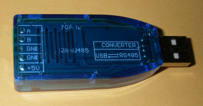
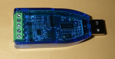
Starting at the mini PC end of the cable, I attached the USB to RS-485 converter to the cable. The converter looks like this:
The image on the left shows the labels for the screw down connections seen on the right. Connections A and B at the top are the modbus connections, then there are two grounds, and then there is a 5V positive feed (taken from the USB port) at the bottom, which I used to power the room temp sensor.
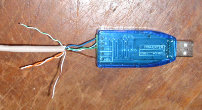
Using a suitably delicate wire stripper (the cores are very thin), I stripped the insulation from four of the cores (doesn't matter which ones, I just made a note of which coloured cable I used for the modbus connection and the power connection), and then made the connections: one of the twisted pairs to the A and B modbus terminals, then two others, one to the 5V positive feed and the other to one of the grounds. I used the blue and blue and white twisted pair for the modbus connections, the solid green for the ground, and the solid brown for the the 5v positive feed. Not my best photo, but this is what it looked like:
I then wrapped the unused wires in insulating tape, to keep them out of harms way, and plugged the USB end of the converter into a USB socket on the back of the mini PC.
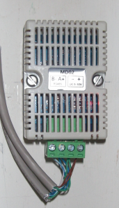
I then went to the room temperature sensor, and made the connections to it. It has four terminals, from left to right B- and A+ (the plus and minus signs are optional, what matters is which is A and which is B) for the modbus connections, and minus and plus for the power supply. because this is a serial (daisy chain) setup, I cut the cable and then twisted together each end of the cores I used, blue, and blue and white, for the modbus connections, green for the ground and brown for the 5V positive feed. Thus the two ends of the blue core got twisted together, and into the modbus A+ connection, and so on. Note that on this sensor the A+ and B- connections are to our Western eyes the wrong way round (we expect A then B not B then A). I made sure the same core connected to the same terminal on both the USB to RS-485 converter and the room sensor, A to A+, B to B- etc. The end result looked like this:
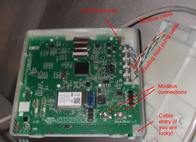
Finally I connected the wired controller. Midea in their wisdom have renamed in reverse order to our Western eyes ('may you live in interesting times') the modbus terminals H1 (for B) and H2 (for A). Here is an overview of what is where after popping off the wired controller from its wall mount by pushing in the tabs at the bottom with a small screwdriver (be careful, the tabs are fragile), before the connections are made:
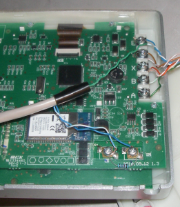
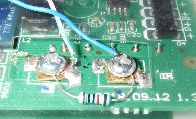
I then connected the solid green core to the E terminal at the top (may not be necessary, I did it for good measure) and then the modbus connections (blue, and blue and white) and resistor to the modbus terminals. Again, I made i connected like with like: the modbus A core (solid blue) goes to the H2 terminal, and the B core (blue and white) to the H1 terminal. The 120 Ohm resistor just goes across the H1 and H2 terminals (again, may not be necessary but I did it for good measure). Once made, the connections looked like this:
Close up of the modbus connections:
I then popped the wired controller back onto its wall mount, being careful not to upset the wiring as I did so, and that's it! Hardware installation done!
The next post, when I can face it, will be how I did the software installation.
Edited to correct typos where spotted, link to Part 2 and add clarification about why I placed the room temp sensor where I did
Midea 14kW (for now...) ASHP heating both building and DHW
Part 4: Software Installation - OS (operating system) and Home Assistant
Disclaimer(and this is entirely my fault): because I did my own installation a while ago, and failed to take adequate notes, these instructions may not include everything needed, or may even be wrong in places (though of course I hope not!). I also failed to take any photos of what I did, hence the lack of images. Nonetheless I post these instructions such as they are as a guide to how to get Home Assistant installed on a mini PC. If not perfect, they are at least a good starting point/guide on how to approach setting up a Home Assistant installation on a mini PC.
Now we have the hardware set up, we can install the software, including the operating system, that will provide the platform for our monitoring system. At the time I did this, getting on for two years ago, I had not developed a finer appreciation of Home Assistant's less attractive features, and as I had to start somewhere, I just went ahead and installed Home Assistant (HA). For this historical reason, I still have HA on my current system. It provides the underlying operating system (OS) which is Linux based, and there are some HA Add-ons that are useful that I still use, even if the bulk of my monitoring is now done with python scripts that run outside HA.
The installation can be done in various ways. The simplest way I found was to download an image (snapshot) of HA and its OS on desktop PC, copy the image and an installation tool to a bootable USB stick, and install HA and the OS from the bootable USB stick to my mini PC. But, as I said above, that was nearly two years ago, and the actual method I used was slightly unusual, and, to my everlasting regret, I failed to take adequate notes. Rather than I try to recreate that slight eccentricity from memory, I suggest you follow the current 'live' Ubuntu HA installation instructions (which are very similar to what I did), available here for a 'generic x86-64' installation, but with a few modifications. These are:
(a) download the HA OS image file from the web page and copy and unpack it to your USB stick before you do the HA OS installation on the mini PC. This saves having to establish an internet connection from the 'live' Ubuntu OS running on the mini PC. When it comes to 'Restore disk image', select the image file you downloaded earlier.
(b) this isn't made clear in the HA instructions, make sure you have a keyboard and monitor plugged into the mini PC while you do the install, either spare ones, or borrow your desktop PC ones temporarily. In normal operation, after you have done the installation, the mini PC will run in headless mode ie no keyboard or monitor, but you do need them to do the installation.
(c) when you first boot the mini PC to get into the BIOS, in addition to setting the boot mode to UEFI, also find the (advanced) power settings, and set them such that the mini PC will reboot itself after a power cut. This ensures minimal downtime if/when power cuts happen, and needs no further intervention from you.
(d) once the installation is complete, reboot the mini PC with the monitor and keyboard still attached. If all has gone well, it will boot to the HA Command Line 'Welcome' screen. While you are there, make a note of the IP addresses and URLs displayed on that welcome screen. You may/will need them later. Then turn off the mini PC, and disconnect the monitor and keyboard (and reconnect them to your desktop if you borrowed them from there).
You should already have a network cable connecting the mini PC to your router (see Part 3: Hardware installation). Now it is time to connect to the mini PC from your desktop PC, and see if all works as it should. Reboot the mini PC, give it a minute or two to get going, and then enter either 'homeassistant:8123' or 'homeassistant.local:8123' or failing that the IP4 address you noted earlier (just the four groups of numbers with dots between them) followed by :8123, something like 192.168.1.55:8123, into your browser. You should see one of a variety of welcome pages depending on what HA gets up to, select the options that allow you to set up an account (Proper Name, username and password etc) and follow the prompts as you see fit (HA will ask a lot of questions, I limited my answers to the bare essentials). Towards the end HA may tell you it has discovered various devices, ignore them for now. Instead, add some useful HA Add-Ons. I added:
(a) Home Assistant Google Drive Backup. This does what it says on the tin, and by setting a schedule, you can have the add-on do the backups automatically. I now have a lot of data on my mini PC, and knowing it is regularly backed up (daily) is reassuring, ditto for the scripts I have added and modified over time. Add it via the Add-On Store button at the bottom of the Add-On Settings page.
(b) Samba Share. This allows you to network folders for file access (for editing, reading data etc) and transfers etc using Windows 'Map Network Drive' in Explorer on your desktop PC. Add it via the Add-On Store button at the bottom of the Add-On Settings page.
(c) SSH & Web Terminal. This allows you to control your headless mini PC from your main desktop PC. This is not added via the Add-On Store (ignore the similar sounding 'Terminal & SHH' Add-On which has far less functionality), and instead go to this main page for the Add-On and then follow the installation instruction on this page. It's a bit of a faff but this Add-On is essential. Once you have added it, go to the Add-On settings page and turn OFF protected mode (it assumes you are an idiot, maybe you are, but I don't assume you are!) because you want full (at least as full as possible) access, and then go to the 'Terminal' page (it should now be in the left hand list/menu on the main HA page) and type this (don't worry what it means, it is beyond us mere mortals) at the ➜ ~ command prompt:
docker exec -it homeassistant bash
which will give you a higher level of access to your mini PC which you will need for some of the things you will do later. Your screen should look like this.
Note how the ➜ ~ command prompt has changed to bash-5.1#. The number may be different, but it must say bash. To test it, type 'ls' and the hit return. You should see a list (ls) of files and folders. You are looking at the Linux equivalent of the command line in Windows. The fact it is Linux is important, you do not use Windows commands here, despite you being on a Windows PC, instead you use Linux commands, hence ls instead of dir /b to get a basic list of files and folders.
You should now have a working HA installation. More importantly, underneath that installation, you have access to the OS HA runs on (Alpine Linux) and so you can do a LOT of things HA won't let you do. Furthermore, you also have direct access to the python installation that HA runs on. This is where you will set up the python scripts that collect your heat pump data. The neat thing about using a HA installation is that all this gets set up for you.
You also need a python installation on your desktop PC to do the plotting. You may already have python installed - check by typing 'python -V' at your desktop PC command prompt, if python is present and accessible, you will see the current python version number. If it isn't you will have to install it, another bit of faffery but worth it, as it means you will get simple but effective plotting for your data. Download an installer from this page. Note that current versions of python don't work on Windows 7, which some people still use. If that includes you, scroll down the page to find a version that will work on Windows 7. Ignore the naysayers baying why would anyone want to use an old OS - it's their cross to bear, not yours. Once you have downlaoded a suitable installer, install it. It may take some time, it may even fail; if it does, take note of the error messages and either correct them, or get assistance from google. Finally test it by typing python -V' at the command prompt to confirm it is present and accessible (you see the version number).
Lastly, as these are also installation steps, add the extra python modules you will need. If you are not familiar with python, do not be alarmed. It is a scripting/programming language that can vary from the very simple and easy to understand (what we will use) to the impenetrably complicated (eg the inner working of a HA installation). If you have ever written a macro, you will already be familiar with the basic ideas, if not, the scripts are just sets of instructions eg read the data from this modbus register address, that python carries out when you run the script. Part of the python 'approach' is that it is very modular, in that once you have a basic python installation, you can add modules, or packages, that extend what python can do. The two that you need to install are 'minimalmodbus', which you will add to the mini PC to enable the modbus communications, and 'plotly', which you will add to your desktop PC to handle plotting your data. There are other modules you will use, but these should already be installed as part of a basic python installation.
To install the two modules (minimalmodbus and plotly), we will use a python utility called pip (these instructions apply to both the mini PC and your desktop PC). This should be available at the command prompt (Windows)/bash prompt (Linux, accessed via the 'terminal' window in HA described above): try typing 'pip list' and hit return, and you should see a long list fly past on the screen. The is a list of all the installed modules pip knows about. Scroll back up the list and look for minimalmodbus on the mini PC and plotly on the desktop PC - they should be missing. To install them, type 'pip install [module name]' and hit return, making sure you add the minimalmodbus module to the mini PC and the plotly module to your desktop PC. You should see a bustle of activity for each one, very likely with some warnings, most if not all of which you can ignore, and then eventually an announcement that the module (and it dependencies) have been installed successfully. Type 'pip list' again and hit return on both PCs to confirm each is present where it should be.
The next post will cover the installation and use of the python scripts that do all the hard work, and at long last, you should see the data coming in and getting stored on your mini PC, along with charts that display the data in useful ways.
Midea 14kW (for now...) ASHP heating both building and DHW
Have been able to find out what information you can get from the grant and also if anything can be 'set' ?
@uk_pete_2000 - no, because I don't have a Grant heat pump. Assuming you have a modbus connection, search online or wherever for a table of modbus register addresses for your heat pump. The table should also give an indication of which register addresses (if any) can be set as well as read. Once you have that table, you can then use python to get the data (the subject of the next post when I do it!).
Midea 14kW (for now...) ASHP heating both building and DHW
@uk_pete_2000 Hi - I've wired up my Grant to get information over modbus for monitoring what's going on (and to eventually provide my own control ... although that's not as simple as it might be), and been running it for over 18 months now. Lots of data.
The register details are detailed here: https://github.com/aerona-chofu-ashp/modbus
(look at the 4 .tsv files ... for convenience I've gathered details from those 4 files and placed them in a .csv file, which you might find useful, and hopefully self-explanatory
).
This post - https://forum.buildhub.org.uk/topic/26269-grantchofu-heat-pumps-and-others-weather-compensation-capabilities/?do=findComment&comment=448413 has some Python code to display (and update) parameter settings, although I'd shy away from altering anything until you know what's going on.
The main issue I found was that the modbus connections are on the external unit, so running the correct grade cable from it to an internal component is perhaps the trickiest part.
Grant Aerona 3 10kW
Thank you @mikefl that was what I was looking for.
No problems with wires (I hope), as we put two sets out when it was installed, so just need to use 3 of these. A couple of the others I might look at setting up night mode and cooling toggles
- 27 Forums
- 2,495 Topics
- 57.8 K Posts
- 413 Online
- 6,220 Members
Join Us!
Worth Watching
Latest Posts
-

@painter26 — they (the analogue gauges) are subtly diff...
By cathodeRay , 22 minutes ago
-

I cannot see the complete rcbo, since the photo is cut....
By Batpred , 35 minutes ago
-

RE: What determines the SOC of a battery?
The answer from Fogstar was crisp. My hypothesis, su...
By Batpred , 44 minutes ago
-

RE: Electricity price predictions
I am always impressed with how you keep abreast of so m...
By Batpred , 54 minutes ago
-

RE: Setback savings - fact or fiction?
I fully understand your reasoning, same steady inputs s...
By cathodeRay , 1 hour ago
-
RE: Humidity, or lack thereof... is my heat pump making rooms drier?
@majordennisbloodnok I’m glad I posted this. There see...
By AndrewJ , 1 hour ago
-
RE: Testing new controls/monitoring for Midea Clone ASHP
@tasos and @cathoderay thanks. I have some history grap...
By benson , 3 hours ago
-
Our Experience installing a heat pump into a Grade 2 Listed stone house
First want to thank everybody who has contributed to th...
By Travellingwave , 4 hours ago
-

RE: Solis inverters S6-EH1P: pros and cons and battery options
Just to wrap this up here for future readers: The S...
By Batpred , 7 hours ago
-
RE: Struggling to get CoP above 3 with 6 kw Ecodan ASHP
Welcome to the forums.I assume that you're getting the ...
By Sheriff Fatman , 7 hours ago
-
RE: Say hello and introduce yourself
@editor @kev1964-irl This discussion might be best had ...
By GC61 , 8 hours ago
-

RE: Oversized 10.5kW Grant Aerona Heat Pump on Microbore Pipes and Undersized Rads
@uknick TBH if I were taking the floor up ...
By JamesPa , 23 hours ago
-

RE: Getting ready for export with a BESS
I would have not got it if it was that tight
By Batpred , 1 day ago
-
RE: Need help maximising COP of 3.5kW Valiant Aerotherm heat pump
@judith thanks Judith. Confirmation appreciated. The ...
By DavidB , 1 day ago
-

RE: Recommended home battery inverters + regulatory matters - help requested
That makes sense. I thought better to comment in this t...
By Batpred , 1 day ago
-
Bosch CS5800i 7kW replacing Greenstar Junior 28i
My heat pump journey began a couple of years ago when I...
By Slartibartfast , 1 day ago
-

RE: How to control DHW with Honeywell EvoHome on Trianco ActiveAir 5 kW ASHP
The last photo is defrost for sure (or cooling, but pre...
By JamesPa , 1 day ago
-

RE: Plug and play solar. Thoughts?
Essentially, this just needed legislation. In Germany t...
By Batpred , 1 day ago
-
RE: A Smarter Smart Controller from Homely?
@toodles Intentional opening of any warranty “can of wo...
By Papahuhu , 1 day ago
-
RE: Safety update; RCBOs supplying inverters or storage batteries
Thanks @transparent Thankyou for your advic...
By Bash , 1 day ago
-
RE: Air source heat pump roll call – what heat pump brand and model do you have?
Forum Handle: Odd_LionManufacturer: SamsungModel: Samsu...
By Odd_Lion , 1 day ago
-
RE: Configuring third party dongle for Ecodan local control
Well, it was mentioned before in the early pos...
By F1p , 2 days ago
-

RE: DIY solar upgrade - Considering adding more panels
I know this is a bit old, but it made me wonder what co...
By Batpred , 2 days ago

