My horrific Samsung heat pump installation and experience
HOW my COP varies with winter Temperatures
The Correlation between my COP and the Outside Winter Temperatures since the 01/01/2025 is -0.9.
The Correlation between my REAL COP and the Outside Winter Temperatures since the 01/01/2025 is -0.6.
i.e COP CROSS-CORR Outside Temperature = -0.9
REAL-COP CROSS-CORR Outside Temperatures = -0.6
Conclusion : The Lower the Outside Temperature the lower is my COP and REAL COP.
With a switch on my Volumiser Tank....................................I can evaluate ........
HOW my COP varies with use of my VOLUMISER TANK.
The Correlation between my COP and the use of my Volumiser Tank since the 01/01/2025 is +0.4.
i.e COP CROSS-CORR VOLUMISER USE = +0.4
Conclusion :MY COP INCREASES with the use of my VOLUMISER TANK.
With a switch on my Volumiser Tank....................................I can evaluate ........
HOW my Energy Loss varies with the use of my VOLUMISER TANK.
The Correlation between my Energy Loss and the use of my Volumiser Tank since the 01/01/2025 is +0.5.
i.e LOSS CROSS-CORR VOLUMISER USE = +0.5
Conclusion :My Energy loss increases with Volumiser tank use.
With a switch on my Volumiser Tank....................................I can evaluate ........
HOW Cycle time varies with the use of my VOLUMISER TANK.
The Correlation between my system Short Cycle time and the use of my Volumiser Tank since the 01/01/2025 is +0.35.
i.e LOSS CROSS-CORR VOLUMISER USE = +0.5
Conclusion :My Cycle time INCREASES with Volumiser tank use.
Overall Conclusions:
1) If I use my Volumising Tank I INCREASE my ENERGY CONSUMPTION AND LOSSES
2) If I use my Volumising Tank I INCREASE my Cycle Time and hence reduce Short Cycling.
3) My Volumising Tank constitutes a BALANCE between Energy Consumed against SHORT CYCLING.
@iantelescope - your determination is laudable! But there are some things that don't stack up here. Some comments:
1. I presume you are using CROSS-CORR to mean Pearson's correlation coefficient (r). Always best to stick with conventional language. It is also a good idea to define terms you introduce eg what is a REAL COP and how does it differ from a COP?
2. Pearson's correlation coefficient is only useful for linear (straight line) relationships between two normally distributed variables. You need to check those requirements apply to you data (histograms, scatter plots, residuals etc).
3. Pearson's correlation coefficient (r) can range from -1 through zero to +1. The closer a correlation coefficient gets to -1 or +1, the greater the correlation. Positive correlations means both variables move together (both increase or both decrease), negative coefficients means they move in opposite directions (as one increases, the other decreases).
4. Your first conclusion:
Posted by: @iantelescopeConclusion : The Lower the Outside Temperature the lower is my COP and REAL COP.
But the r values you give are negative. That means they move in opposite directions, ie the higher the outside air temperature, the lower your COP! Something is wrong!
5. Next paragraph:
Posted by: @iantelescopeWith a switch on my Volumiser Tank
What is this switch? What does it do? Turn a light on or off somewhere? Do you mean a pipe work bypass so you can include/not include the volumiser?
In any event, the r value for this is low (0.4). Nothing to see here, as they say. But the real problem is that something that switches is a categorical variable (on, off), not a continuous variable. You can't use standard (Pearson) correlation here.
6. The same problem (volumiser on/off is a categorical variable) applies to the remaining paragraphs, they can't tell us anything.
It is also not clear how you measured Energy Loss. Energy loss itself is not easy to measure, we end up using a proxy eg energy out (delivered to the house). It is always a good idea to explain what you did.
I offer the above in a spirit of positive criticism, even if it seems negative in content, because I do applaud your wish to understand your system better. Modern spreadsheets make it easy to do statistical analyses, but they don't tell which analysis to do. That needs a little work before actually doing any number crunching.
If you can post a sample of your data (wrap it in a zip file if need be), I'll have a look at it and see what analyses might work.
Midea 14kW (for now...) ASHP heating both building and DHW
Many thanks for your excellent reply cathoderay. I appreciate your measured contribution.
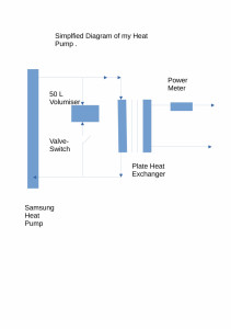
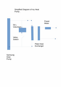
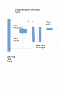
1) A greatly Simplified Diagram of my "system".......
2) COP and Real COP?
I measure COP :
Posted by: @iantelescopeA greatly Simplified Diagram of my "system".......
I don't think that is a volumiser, it's a bypass! Volumisers go in series and solely act to increase volume...
Midea 14kW (for now...) ASHP heating both building and DHW
Volumisers, Serial and Parallel
1) MCS ADVICE. Avoid Short Cycling by increasing the Water Volumes on Heat Pump pipework.
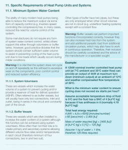
2) Samsung advice on increasing Water Volumes:
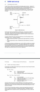
3) MCS Advice on the Size of SERIAL Volumiser/Buffer tanks required to avoid Short Cycling.
WARNING. Note the MCS advice relies on the assumption that :
" a fluid Temperature drop of 5 C is ACCEPTABLE ".
In some cases , including my own , a water drop of 5 C IS NOT ACCEPTABLE.
My Heat Pump supplies Water ramping between ~35C and 42 C .
With a 5 C Serial Temperature drop the Ramping Temperature would be reduced to ~30 C .. 37 C .
4) DECC Recommendations for Parallel Buffers.
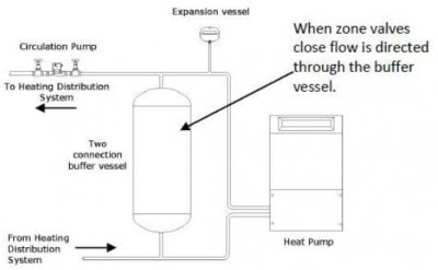
5) Kensa Recommendations for a Parallel Buffers/Volumisers.
6) The Advantages and Disadvantages of Serial Volumisers.
a) Serial Volumisers should be used where a 5 C Temperature Drop is Acceptable.
b) Serial Volumisers , with their small Temperature drops, circa 5 C, have much reduced losses .
7) The Advantages and Disadvantages of Parallel Volumisers/Buffers.
a) Parallel Volumisers are MUCH easier to install than Serial Volumisers.
b) Parallel Volumisers/Buffers , operating at Temperatures of 35 C to 45 C , have much greater losses.
c) Parallel Volumisers/Buffers , CAN briefly, during switching , operate at the Temperatures of the Water heater / Legionnaires Water Temperatures , with even greater loss.
In my experience, with a Plate Heat -Exchanger isolating, and Protecting, my Heat Pump from my Radiator circuit my Water Volume is/was 6 Litres!
This 6 Litre volume then producing a cycle time of 8 minutes.
8) DE-icing, Frost , Cloud formation
Samung-Dallium later gave DE-Icing as an additional justification for the installation of a Volumiser/Buffer.
The Additional 50 Litres of hot storage water at 35 C to 47 C providing further protection against Frost.
During de-icing the Water stored in the Hot Water Tank is dumped back into the Heat -Pump along with the Energy stored within the Volumiser/Buffer.
A 50 litre Parallel Volumiser/Buffer was selected by SAMSING-DALLIAM later installed by my then Installer .
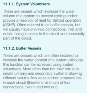
@iantelescope - I think you are still confused about the difference between a volumiser and a buffer tank. Take this from the MCS guidance you posted:
A volumiser is two port and in series, and is there to increase system volume (and in turn reduce cycling and/or provide a heat reserve for defrosts). MCS do say they are 'often referred to as buffer vessels' - they might have done better to write that as 'often incorrectly referred to as buffer vessels'.
Buffer vessels (tanks) on the other hand are (more often than not) used to create primary and secondary systems (circuits), and therefore have a minimum of four connections, two in and two out.
The vessel in your system diagram has two connections, and is in parallel, and therefore matches neither of the above descriptions, which is why I called it a bypass.
The DECC report is over 12 years old, and applies only to heat pumps with single fixed speed compressors and what appears to be external thermostatic on/off control (albeit based on the flow/return temps). You cannot extrapolate the results to more modern modulated compressors, even if the report makes sense, which I am not convinced it does.
The Kensa diagram you posted shows a similar setup to yours, and all but explicitly says it's purpose is to act as a bypass: when zone valves close, flow is directed through the buffer vessel. Here they have fallen into the trap of calling a bypass a buffer vessel. True buffers have four ports, the vessel shown has two, ergo it is not a buffer vessel.
The rest of your post I regret to say appear to be mumbo-jumbo that makes little if any sense to me. It may even be an answer in search of a question!
You were going to explain how you determined COP and REAL COP and then your earlier post came to an abrupt halt. Can you perhaps complete that section?
Midea 14kW (for now...) ASHP heating both building and DHW
My System Simplified:
Correlation and Statistical Independence?
1) Measuring the Correlation between the use of a Volumiser/Buffer and COP.
Using a Spreadsheet I have performed a Correlation between Volumiser use and COP, giving a "R" value , between Volumiser use and COP .
Volumiser use , a Binary Value 1/0 , set by operating the Valve/Switch connected to the Volumiser/Buffer Tank.
My COP is measured from the front panel of my Samsung Heat Pump as
COP = Energy Generated and displayed on the front panel of my Heat pump during a 24 hour period / Energy Consumed during the same 24 hour period.
The R value for this correlation is +0.4 .
From the +, Positive correlation ,I conclude that the COP increases with Volumiser/Buffer use.
2) Measuring the Correlation between the use of a Volumiser/Buffer and REAL-COP.
My REAL-COP is measured as :
REAL- COP = Energy Displayed on my Sharky Power meter during a 24 hour period / Energy Consumed, as displayed on my Heat Pump during the same 24 hour period.
The R value for this correlation is = -0.07.
From the approximate R ~0 , I conclude that my REAL-COP is uncorrelated with Volumiser/Buffer use.
2a) R=0 and Variable Independence ?
A zero , 0 , value for R , would , here, imply the independence of Volumiser/Buffer use from COP.
2b) R=0 and Statistical Independence ?
A zero , 0 , value for R , would , here, NOT give any information about the Statistical independence of Volumiser/Buffer use from COP.
3) I have measured the Correlation between Maximum Outside Daily Temperatures and Energy Consumption as , R = -0.95
I have measured the Correlation between Minimum Outside Daily Temperatures and Energy Consumption as , R = -0.85
From the Negative R value I conclude that Total Energy Consumption is STRONGLY correlated , as expected ,with falling outside Temperatures.!!
4) I have measured the Correlation between COP and Maximum Outside Daily Temperatures , R = -0.90
From the Negative R value I conclude that COP is STRONGLY correlated, as expected with FALLING outside Temperatures.!!
5) I have measured the Correlation between REAL-COP and Maximum Outside Daily Temperatures , R = -0.72
From the Negative R value I conclude that REAL-COP is STRONGLY correlated, as expected , with FALLING outside Temperatures.!!
1) Regardless of name , be it Buffer or Volumiser ......the point is that the Volume of water is, and MUST be , increased from 6 liters.
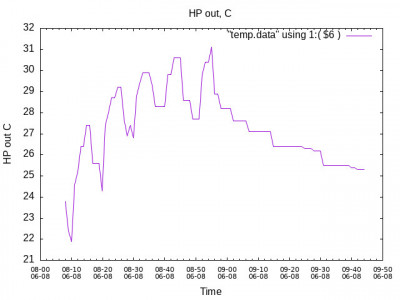
2) Regardless of when the DECC report was prepared , the exponential fall in Water Temperature defines the Heat Pump Period, and Short Cycling , as also shown in the MCS contribution.
3) The Heat Pump period is defined by the time taken for the Water Temperature to fall below the lower thermostat Temperature .
The Heat Pump Water Output Temperature is shown on the graph for 8th June 2023.
If the Water Volume contained within the pipes plus the Volumiser/Buffer is V .
The Mass of Water will be V X Den. In the Metric system Den =1.
If the Water has a specific Heat of Spec_Ht
and the Heat Pump is producing K kw then
Energy released from water during refrigeration period, P ( kwh) = Power X (T2 -T1) = K X ( T2 - T1) = (Spec_Ht X V X (C2-C1) )
Period (P) = T2-T1 = ( Spec_Ht X V X (C1 -C2)) /Power
i.e. the Time taken, P , to release all of the stored energy is proportional the Volume of Water , V .
Note , as with the MCS and DECC I am neglecting the Exponential for simplicity.
4) Frost
The Volumiser Tank was selected by SAMSUNG-DALLIUM to Dump The ENERGY STORED IN THE hot water system and the Buffer tank into the Heat Pump Cooling fins.
On frost being detected the Hot water Cylinder releases the ENERGY stored within the HOT Water Tank through the heating coils , now acting as a Heat Exchanger !.
The Energy from the HOT Water tank is Dumped into the Heat Pump with the energy stored within the buffer also released.
5) Responsible?
This system was , in part, designed by SAMUNG-DALLIUM and "installed" by my then "installer", with my "installer" being Struck OFF by the MCS and the NIC on three occasions for his efforts.
My "installer" initially insisted that he alone, NOT SAMSUNG was responsible for the installation of the Buffer Tank, Thermostat, Water Flow sensor and Expansion vessels, ALL of which were found to be missing at the initial installation.
.
Posted by: @iantelescopeUsing a Spreadsheet I have performed a Correlation between Volumiser use and COP, giving a "R" value , between Volumiser use and COP .
Volumiser use , a Binary Value 1/0 , set by operating the Valve/Switch connected to the Volumiser/Buffer Tank.
As you haven't specified which correlation method you have used (a number exist), I assume you have used Pearson's correlation coefficient (which is r not "R" by the way for a sample), which is the most common. Look up when it can and when it shouldn't be used.
Midea 14kW (for now...) ASHP heating both building and DHW
Posted by: @iantelescopeRegardless of name , be it Buffer or Volumiser ......the point is that the Volume of water is, and MUST be , increased from 6 liters.
Names do matter, because what they refer to are different things. Sloppy language = sloppy thinking. If you need to increase the volume of water, then you need a volumiser that is only a volumiser, and that means plumbed in in series, two ports only. What your system diagram shows is a large radiator on the primary circuit. If the valve is open and it's resistance is low, it will steal water and therefore heat that would otherwise have gone to the PHE. I am not sure why both ports have arrows pointing inwards, because that can't be the real flow.
6 litres by the way is a very small system volume. Some of my larger rads alone hold twice that much. Are you by any chance counting only the primary circuit volume? If so, that is not the system volume (OK PHEs do complicate things, but the volume the secondary circuit does come into it).
The rest of your post is an exceptional piece of gobbledygook, even by your own exceptional standards! I note that you "neglect[ed] the Exponential for simplicity", a mercy for which we must all be very grateful.
I am still not convinced your system is short cycling. Can you please post a chart with time on X axis, and both flow and returning water temperature on the Y axis over a reasonable but not too long recent period, say 12 hours, adding a note of the outside air temperature range during the charted period, that you believe shows your system is short cycling? If there isn't a problem, then it doesn't need fixing...
Midea 14kW (for now...) ASHP heating both building and DHW
- 26 Forums
- 2,418 Topics
- 54.8 K Posts
- 192 Online
- 6,098 Members
Join Us!
Worth Watching
Latest Posts
-
RE: Ecodan Pump Issues… Circulation pump turns off when heat pump compressor turns off
@jamespa sorry James, yes larger surface area, messing ...
By ASHP-BOBBA , 8 hours ago
-
RE: Advice for a novice on Mitsubishi Ecodan 6kW
In the Home Assistant firmware the data points...
By F1p , 8 hours ago
-
RE: GSHP WOES! Midland based engineer recommendations?
@johnbroome if it is not the pressure in the expansion ...
By ASHP-BOBBA , 8 hours ago
-
RE: Installer Fitted 9kW Instead of 11kW Heat Pump and Changed MCS Paperwork - What do I do?
In recent cold weather th...
By JamesPa , 8 hours ago
-
So I hear the export MPAN that UKPN assigned should be ...
By Batpred , 11 hours ago
-
RE: Recommended home battery inverters + regulatory matters - help requested
From what I read, the Solis has a very long list of err...
By Batpred , 11 hours ago
-
RE: Ideal HP290 14kW ASHP - how to optimise
Roughly this should cost you £250-£300 per peak month a...
By ASHP-BOBBA , 12 hours ago
-
RE: New Daikin 11kW Altherma 3M install - is it working as it should?
@toodles Thank you for your input. As the days have got...
By Synthbuilder , 16 hours ago
-
RE: Fan unit Making terrible noise HELP!!
@gutoffowc Oh no, sorry to hear that, are you in the Ke...
By ASHP-BOBBA , 18 hours ago
-

RE: Sunsynk Whole House Backup Issue
@sheriff-fatman - could you please re-post that in the ...
By Transparent , 18 hours ago
-
RE: Running my new Nibe ASHP efficiently
I didn't. I spent a while manually messing around with ...
By jamieheatpumpnew , 20 hours ago
-
RE: I’m glad the cold spell is over!
I comparison with the 65kWh used above yesterday was on...
By Judith , 20 hours ago
-
RE: Octopus Cosy 12 Heat Pump Regret: Incredibly Loud, Poor Heating & Constant Hum - Help!
I should think so, I thought that pretty much universal...
By JamesPa , 21 hours ago
-

RE: Setback savings - fact or fiction?
I'm also inclined to look into how a defrost is actuall...
By cathodeRay , 21 hours ago
-
MLCP (Multi-Layer Composite Pipe) for ASHP
@editor nope. The info you reported was sufficient for ...
By iotum , 1 day ago
-
RE: Experience - New Build / Complete New Heating System
@vincro I would be surprised if it is much above 5 to 6...
By ASHP-BOBBA , 1 day ago
-
RE: Post-Traumatic Heat Pump Stress Disorder
Yes bang on and maybe I can illustrate that by way of e...
By iotum , 1 day ago
-

