We purchased a small plot of land in Roche, Cornwall, in 2010 with the potential to accommodate a single house subject to planning permission. The plot included a derelict, stone-built, lime kiln and was dissected by a small stream.
We wanted to create a home within a limited budget that would be suitable for our future needs and retirement, which meant we needed something that was low maintenance, warm and energy efficient.
After considerable time rebuilding the lime kiln, re-routing the course of the stream, designing the house and getting planning permission, we finally started building the house in 2015 and moved in during December 2016.
Design
Having previously been in properties with underfloor heating I was convinced that this was the way forward for low energy input and comfort, and most suited to heat pumps due to the low heating circuit temperature. We also wanted a wood burner for back up and occasional use.
With little knowledge of heat pumps at the time, I learned that ground source heat pumps (GSHPs) had a higher COP than air source heat pumps (ASHPs) so we started looking at options that were available to us, seeking information and advice from suppliers.
In particular, I found plenty of useful design information on the Kensa Heat Pumps website and later from their technical team. From an estimated heat calculation, it soon became evident that I did not have sufficient land to install traditional ‘ground source’ slinkys. Boreholes were going to be expensive and the stream was not sufficient in size for closed-loop coils within the river bed.
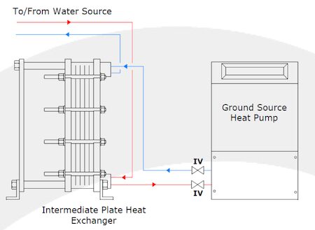
Then I read about an open-loop system using a plate heat exchanger as the interface. Having worked in an engineering career and having knowledge of heat exchangers, the design then started to materialise.
Challenges
- Design of river water chamber/sump to provide volume and clean water for the primary circulation pump
- Abstraction regulations for the water course
- Selecting a suitable pump for the river water duty – efficiency and quality
- Location of the heat pump to minimise noise
- Location of buffer vessel and all ancillary equipment
- Location of DHW (domestic hot water) tank on first floor due to weight and structural requirements
House specification
Our house is 158m2 spread over two floors. It’s a timber frame construction clad in block/brick, foil backed PU foam insulation to floor, walls and roof space, 3.5kW solar PV system, with a calculated maximum heat demand of 7.1kWh.
Heating specification
We have wet underfloor heating running to all ground floor spaces, fan convector radiators in bedrooms and towel radiators in bathroom and en-suite. We also have a 3kW wood burner as secondary heat source.
The final design incorporates the following components:-
| Component | Size & Specification |
| Heat pump | Kensa compact 6.0 kW single phase |
| Underfloor system | JG Speedfit system including manifolds and pumps |
| Buffer vessel | 150l stainless steel insulated cylinder |
| DHW tank | 305l stainless steel insulated cylinder with heating coil and immersion heater |
| Three bedroom radiators | Smiths Eco Powerad 1500. 0.9 kW @ 40 deg.C |
| Two towel rails | Adige Belloza 554, 1237W @ Delta 60 deg.C |
| Raw water pump | 35W variable speed submersible aquarium pump. 240V AC set to flow 18 l/min, @ 14W absorbed |
| Heat exchanger | UKE 6 kW stainless steel unit with 17 plates |
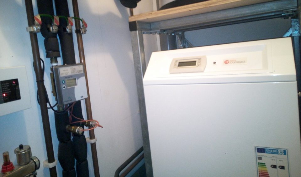
Installation
The heat exchanger is installed in the garage, with underground pipes connecting it to the river water pump and also the heat pump in the main house. The heat pump is quite noisy, and despite being advised that it would be suitable for installation in a utility room, we decided to locate it in what was originally designated as a cloakroom off the utility room to house the heat pump, manifolds and in fact all other plumbing and electrical services for the house. This was a good decision as there was no other space for the buffer vessel.
Also keeping all the services in a dedicated boiler room has kept our utility room clear and tidy. From a noise perspective, the heat pump is slightly noisier than the old oil boiler we had in our previous property, but being behind a closed door in the boiler room reduces the noise to an acceptable level.
The airing cupboard incorporating the DHW tank is on the first floor directly above the boiler room and over a main structural beam.
Programmable thermostats are installed in each room downstairs and on the first floor landing.
The fan convector radiators installed in each of the three bedrooms and the towel radiators are in a permanent open circuit. These convectors receive heat whenever the circulation pump is on, i.e. when any thermostat is demanding.
The fan convectors, when first installed, did not operate satisfactorily as a result of having a fixed temperature switch set at 35C. This temperature switch controls the fan when the radiator is receiving heated water. However, as these are in circuit with the underfloor system which is set to deliver at a maximum of 32C the fans were not coming on. To overcome this, I fitted a separate digital temperature controller to each radiator in place of the original switch, set to start the fan at 28C and stop it at 24C.
The DHW tank is heated once a day on a timer. A diverter valve changes over to the DHW circuit and switches the heat pump onto DHW mode, i.e. 50C. Following this period, the electric immersion heater timer takes over to boost the DHW tank to 65C. Although this is only recommended to be done weekly to avoid legionella, we boost daily to maintain hot water rather than just warm, but both timers are set to heat water between 12:00 and 14:00 when the solar PV benefit is maximised.
Operation
The programmable room stats are set at between 19 -21C. When any stat drops below its target temperature, the UFH controller starts the underfloor circulation pump and opens the corresponding valve(s) to the underfloor circuits. The heat pump will start when the return water from the underfloor circuits drops below 22C and will continue to raise the temperature to 32C unless all rooms reach the target temperature and there is no longer any demand.
On the external side of the system, when the heat pump is running, it circulates a water and glycol solution through the secondary side of the heat exchanger. The secondary circuit incorporates a flow switch which detects flow from the heat pump and will start and stop the external river water pump on demand.
Reliability
In general, the system has proved to be reliable. We tend to get a fault indication on the heat pump relating to ‘low ground water pressure’ which requires us to open a small top-up valve until the pressure gauge indicates over 2.0 bar. This normally happens annually when we start using the heating each autumn
Initial problems were encountered with the river water pump. In simple terms, due to very small demand, it would not be energy efficient to have a larger robust pump for this duty, and most small pumps tend to be cheap plastic throw-away types for fish ponds and water features. After a few initial failures, I came across a submersible aquarium pump with an electronic speed controller which can be set to the desired flow.
We have had two failures of the programmable room stats which have been replaced under warranty.
We also recently experienced a failure of the UFH control unit, just out of warranty, which despite demands from the stats and the circulation pump starting there was no start signal to the heat pump. A replacement control unit was sourced and successfully fitted.
Operating costs
In average winter conditions, the heat pump operates for approximately 5 minutes every 30 minutes. During peak demand when outside temperature are at -5C the heat pump operates for approximately 5 minutes every 15 minutes.
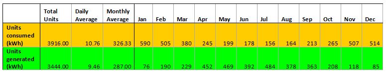
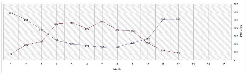
I do not have discreet actual power measurements, for heating and DHW but the following is based on monthly meter readings for both electricity supply and solar PV generation.
2019 Energy Balance
The Kensa 6kW heat pump has a rated power consumption of 2.1kW and the immersion is a 3kW unit. Acknowledging contribution by the solar PV generation, part of which will also be consumed during daylight hours, and without a ‘smart meter’ the following table estimates the maximum (winter) and minimum (summer) consumption.
| Monthly | Daily | Heat Pump | Immersion | Other |
| 590 (max) | 19.0 | 12.6 | 3.0 | 3.4 |
| 180 (min) | 6.0 | 0 | 3.0 | 3.0 |
Despite not currently being able to record and analyse our energy consumption and generation with sufficient granularity, with the monthly readings, annual summary, and year on year comparison, we are confident that our energy system is performing efficiently and as predicted at the design stage.
| kWh | Cost / FIT income – £ | |
| 2020 consumption | 3914 | 715.60 |
| 2020 generation | 3519 | 591.28 |
| Balance | -395 | -124.32 |
In Reply to questions from Derek Marsh:-
Being a GSHP, we do not have an external unit with a fan. Our compressor unit is installed indoors and receives a flow of Glycol solution in a closed loop to an external plate heat exchanger. The control is a simple cascade system whereby, the controller calls for the heat pump to increase the temperature in the underfloor circuit. The compressor and the glycol circulation pump starts, and a flow-switch on the glycol circuit switches on an external water pump which in basic terms pumps water from a stream into the primary side of the plate heat exchanger, from which it flows back to the stream under gravity.
Regarding controls, we have 4 digital room thermostats, which are set to the required room temperature. When the measured temperature drops by 0.5 C below the set-point, the stat calls for more UFH to that room. What should then happen is that the heating controller switches on the UFH circulation pump and opens the corresponding solenoid valve/s pertaining to the room demanding. Warm water stored in the buffer tank is then circulated by the UFH pump until the area demanding heat reaches it’s set-point.
The heat pump compressor and its cascade control of pumps will be called when the UFH water temperature falls below its minimum setting of 23 C. It runs then until the UFH water temperature reaches 32 C. This is how it should work. However in practice the control of the heat pump is not currently making full use of the buffer vessel, as a result of the UFH controller has a simple ‘enable’ relay output to the heat pump, which switches it on sometimes unnecessarily. This is due to the fact that the UFH temp sensor is in the actual heat pump unit not in the buffer tank where the heated water is stored. Although installed to the manufacturer’s instructions, it means that the compressor is working more often than it needs to, so I am planning to add another controller at some point to improve efficiency
Great Article! I live at a property with a stream on-site and use well water, which could support an open loop system. It looks like you’ve solved the water problems by using heat exchangers… everything I read said to be careful about the water quality. Cool solution.
Hi. Thanks for your comments. The heat exchanger is a stainless steel plate type, and although the materials in contact with the water are resistant to most chemical contaminants, the risk is from either biological organisms or soluble chemical elements. Iron being one of the common ones. I would recommend getting a water sample analysed. In our case, the stream is from a spring, and low in contamination with the exception of silt and turbidity during periods of high rainfall, as there are some surface water drains entering the stream upstream of our property. I have reduced the impact of storm debris by careful design of the intake point and collection sump. For annual maintenance I drain and clean out the sump and back-flush the heat exchanger and pipework with tap-water. The supplier advises that the heat exchanger can be flushed with a dilute solution of sodium hypochlorite (bleach), but I have not found this necessary for our water source. It is a good solution, but is highly individual to each site, so the system design is critical, in particular access for maintenance.