I was recently asked by the organisers of PowerEx Live to do a presentation for them in December 2022 outlining how to install heat pumps correctly so that they work properly and deliver good winter and seasonal COP. For a number of years I have personally been advocating a direct heating design strategy for the installation of heat pumps that goes against most industry expert and manufacturer recommendations.
The heat pump industry has got a relatively poor reputation regarding performance, reliability, comfort and installation costs in the UK. This has been clearly illustrated by a number of reports conducted by:
The Energy Saving Trust Getting warmer: a field trial of heat pumps in 2010 with a mid-range efficiency of around 2.2. This report was withdrawn by government as the industry stated that it was woefully inaccurate.
The Energy Saving Trust, the heat is on: phase 2 heat pump field trials (a replacement for the previous study) which reported a SPFH4 of 2.45.
The UCL Energy institute analysis of the RHPP in 2017: reported a SPFH2 value around 2.65.
And finally, the RECC’s (Renewable Energy Consumer Code) report of the analysis of Ofgem’s ‘Metering for Payment’ Data conducted in 2020 which reported an SPF of 2.67.
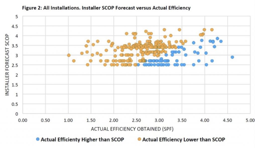
Here is a scatter graph from RECC’s document showing the performance of heat pumps versus the predicted SPF performance published by the various manufacturers and supplied to MCS. This includes both air and ground source installations. Ground source has a marginally better performance at 3.15.
Predicted manufacturers’ SCOP performance levels on various 12kW units with a flow temperature of 35C were provided as follows:
- Mitsubishi Ecodan 3.99
- Samsung 4.75
- Daikin Altherma 4.3
- Nibe 4.2
- Panasonic T Cap 5.09
- Valiant 4.88
Average: 4.54
Based on the declared figures above and the actual figures from the field trials there is a significant difference between predicted and actual performance levels. The difference is close to 200% more heat harvested from the atmosphere in the predicted figures. This is in part due to the way manufacturers and merchants have been recommending the installation of heat pumps.
SPFH4 refers to the seasonal performance factor, or average annual efficiency of the entire system. For instance, the SPF in the last trial analysis was 2.67 which means that for every 1kWh of electricity used, 1.67kWh of free heat is harvested from the air, ground or water.
This results in a seasonal performance factor (SPF) or seasonal coefficient of performance (SCOP) of 2.67 where for every 1kWh of electricity you use, you produce 2.67kWh of heat. By comparison, an electric fan or bar heater which produces 1kWh of heat for every 1kWh of electricity used has a SCOP of 1. Also, 1kWh hour of electricity is the equivalent of 1 unit of electricity purchased from the electricity supplier, measured on the household electricity meter.
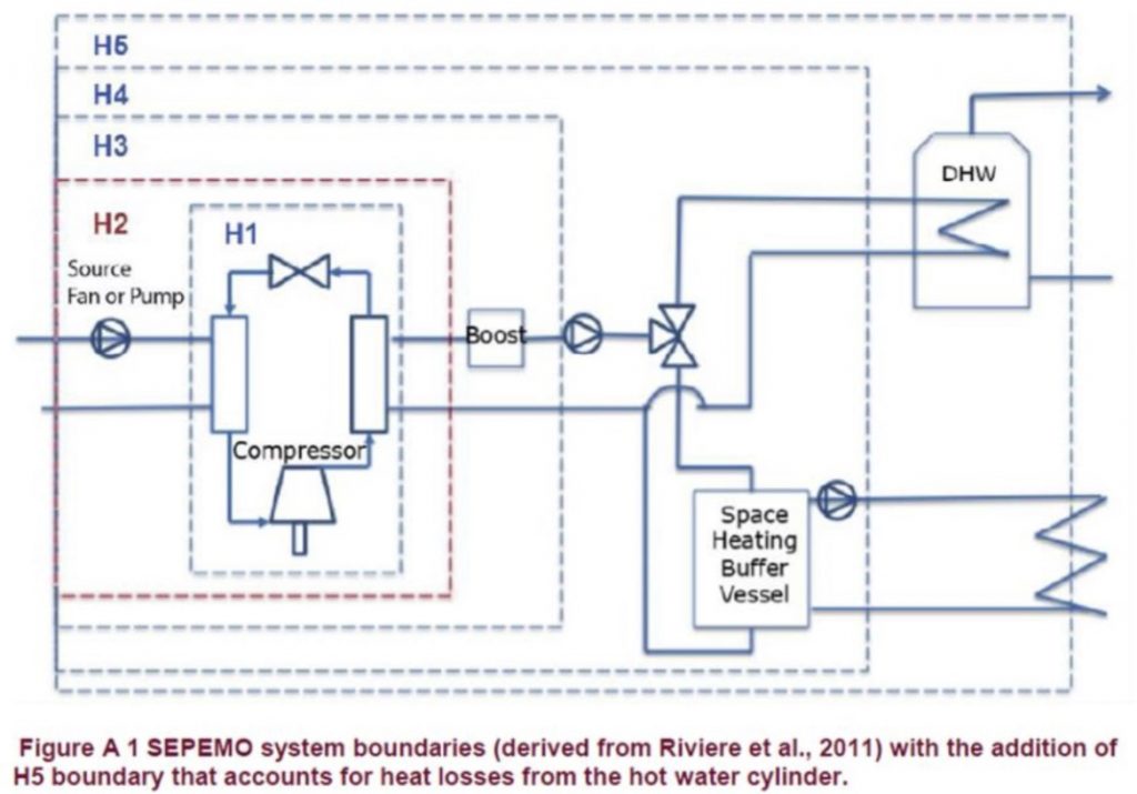
H5 refers to the boundary of the installation being measured, and what energy using equipment is included in the sample to work out the overall efficiency. The relevant boundaries are depicted in the illustration below for clarity.
What all the aforementioned reports show is that there has been little improvement in actual real life heat pump performance from 2010, regardless of what the manufacturers and the industry are saying, and it is surprising considering the significant improvement in the technology over that period.
Based on the above irrefutable evidence of poor performance and Heacol’s history of high-performing installations with SPFH4 performance levels of 4 plus, I decided to take up the challenge and show people what is happening.
To achieve this, I decided to use the test rig that I developed in conjunction with Ulster University to test our heat box unit (a direct combi boiler replacement producing all heating and instantaneous hot water with a heat pump, which is currently in development) to conduct like-for-like tests on three different heat pump installation strategies.
Domestic hot water production was excluded as this is generally a fixed output, temperature and load in all installations, and performance levels are well documented by the manufacturers. In the UK it is also a relatively small portion of the annual heating load.
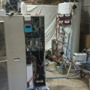
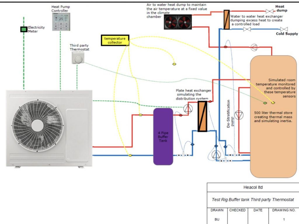
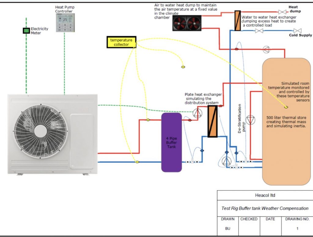
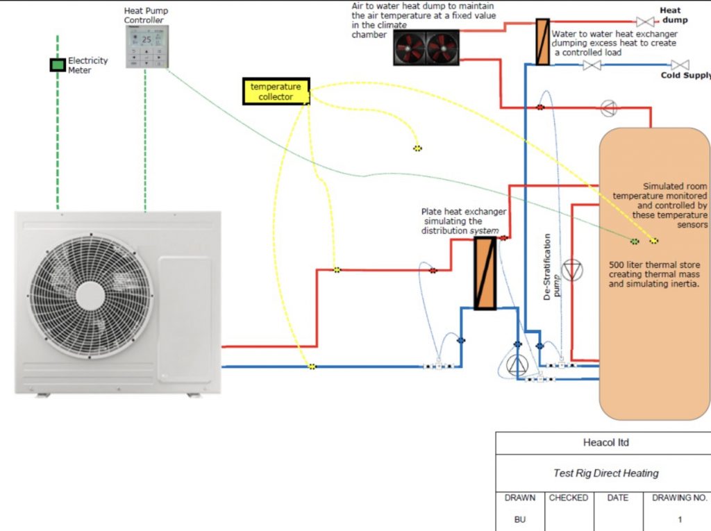
To obtain a usable set of data I decided to exclude the heating system so that like-for-like testing could be conducted to show what effect the recommended buffer tanks have. The test rig comprised of a 500-litre thermal store that simulates the thermal mass of a property, a plate heat exchanger simulating the radiator or under floor heating system heating the property (the thermal store) and the heat source attached to this plate.
For the heat sourced we use the latest Panasonic R32 heat pump connected to the heat exchanger in three different ways, using three different control strategies. In addition to this there were water-to-air and water-to-water heat dumps simulating the load placed on the system by cold weather. All tests were conducted at the H4 boundary.
The first system is the most common piping layout control strategy installed in the UK for the last 10 years – this is a four-port buffer tank controlled by a third party thermostat.
The second system is also a common layout and control strategy using the four-pipe buffer tank controlled by weather compensation, a constant flow temperature which varies depending on the external ambient temperature.
The third is a direct system into the distribution system from the heat pump controlled by the heat pump’s controller, maintaining a constant temperature in the thermal store (house).
In all scenarios we maintained a constant temperature of 20C in the property (thermal store). These three tests enabled us to evaluate and compare the performance and efficiency of each installation strategy in a like-for-like environment without any other interference.
Data was collected in up to 5 second intervals from three class 1 heat metres and one class 1 electricity metre. We were also able to collect the data from the heat pump showing the compressor speed and other relevant settings and readings. The data collected includes all energy used associated with heat production. This data was collected and analysed to produce the results.
The following diagrams show the three different piping methods that I used to during the tests.
Buffer tank and third party thermostat
Buffer tank with weather compensation control
Direct heating with the heat pump controlling the internal temperature
Testing Method
The main aim of this test was to obtain an accurate, verifiable and repeatable result at the best possible performance level for that particular piping scenario while maintaining as many fixed variables as possible. The permitted variables were:
- Piping layout up to the distribution system in three different scenarios
- Flow temperature to achieve the fixed state temperature within the thermal store
To achieve this, we installed the system inside my modern, well-insulated industrial unit and created a fixed climate condition at 7C. The reason for this is that all standard tests on heat pumps are conducted at this temperature using the BS14511 test standard (as seen on all manufacturers’ published data).
This temperature was maintained electronically by an air blower, removing heat from the thermal store and heating the unit which was being cooled by the heat pump.
Each test was set up to maintain a steady state of 20C within the thermal store by adjusting the weather compensation curve within the heat pump controller until the steady state was achieved, starting at a low point moving it up slowly until the desired temperature in the thermal store was achieved and maintained.
This was done to prevent an over supply of heat which would reduce performance and increase cycling of the equipment and a further reduction in performance.
The load was determined using the heat loss calculations from one of our projects which was completed a few years ago. The house in question is a mid-40s cavity-filled, 2-storey house with double glazed windows and 300mm loft insulation. The predicted heat load at -3C was 10.63kW and by changing the external temperature from -3C to 7C the predicted heat loss came down to 6.5kW.
During all three tests we removed 6.5kW constantly from the thermal store simulating this heat loss. This was achieved by heating the air and topping that up with a cold water dump through a plate heat exchanger. The flow rate between the plate heat exchanger and the thermal store was also kept the same during all three tests – we did alter this flow rate to see the effect on the system.
The altering of the flow rate fairly accurately matched the behaviour patterns we have witnessed from various heating system designs. We settled on a flow rate that simulated a radiator system maintaining the return temperature of the 20C room temperature, and the flow temperature varying based on the heat supply temperature just as a radiator system would react to the room.
The temperature difference between the flow and return temperatures (Delta T or ΔT) from the heat pump was maintained at a fixed 5C by the heat pump (the default setting on the Panasonic unit).
The flow rate exiting the buffer tank was set to 30 litres a minute, which is the flow rate required to move 10.63kW of heat (the house’s peak load at -3C ambient temperature) at a ΔT of 5.
Results
Buffer tank and third party thermostat
Buffer tank with weather compensation control
Direct heating with the heat pump controlling the internal temperature
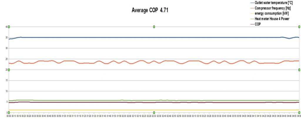
The results clearly show a significant difference of performance between the three different piping and control strategies.
The results are based on a steady state COP for all tests and the minimum off time for a compressor of 15 minutes which matched the manufacturer’s maximum number starts per hour.
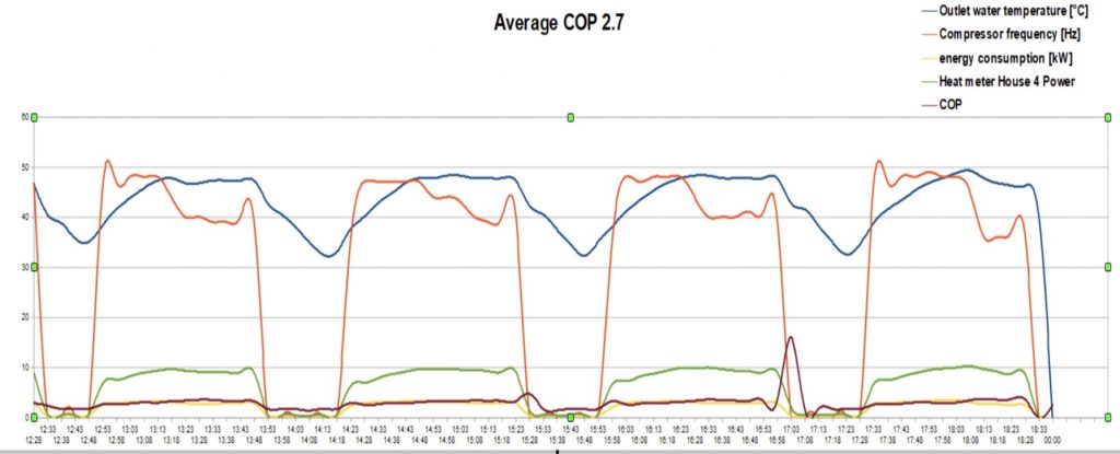
Test 1: shows an installation with the highest flow temperature, cycling in a pattern of approximately 1 hour running and 20 minutes off. This is caused by the on-off thermostat reaching the set point and switching the unit off and waiting for the 2 degree drop in the measured temperature before switching the system on again. The inclusion of the secondary circulator’s power within the performance data.
The COP averaged 2.7 over the period of the test sample.
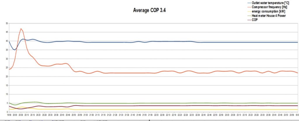
Test 2: shows a steady performance level with a flow temperature lower than test 1. A steady heat pump output and performance level. The inclusion of the secondary circulator’s power within the performance data.
The COP averaged 3.4 over the period of the test sample.
Test 3: shows a steady performance level with a flow temperature lower than test 1 and 2. A steady heat pump output and performance level.
The COP averaged 4.71 over the period of the test sample.
Why is there a significant difference in performance?
This question is relatively easy to answer.
Firstly, when a compressor starts it takes some time before it reaches a steady state position where it maintains best performance. This can be clearly seen on the first graph with the relationship between the compressor speed and the heat output. The compressor speeds up very quickly but the heat output gradually increases – this results in a significant reduction in performance every time the compressor starts. The more the compressor starts, the worse the overall average performance is. In part load conditions the compressor on time will be reduced resulting in more starts per hour/day and the associated drop in performance.
The second reason is associated with the 4-pipe buffer tank (system separator or plated exchanger) and the secondary circulator installed to circulate the heat around the property. The secondary circulator must be designed to supply sufficient heat to the radiator system distribution system to meet the maximum demand the system is designed for. In majority of cases the secondary circulator is a fixed speed pump and, in this example, would be pumping 30 litres a minute whenever the system is on. This pump uses electricity and could cost in the region of £150 per year to run with current energy costs. However, this is not the only problem in part load conditions with most modern heat pumps they control the delta T of the flow and return temperatures to produce optimum performance from the heat pump. To control this optimum delta T the heat pump varies the flow rate depending on demand.
In this trial our test was based on external temperature of 7C, therefore this was part load conditions and the heat pump only had to supply 6.5kW of heat energy to satisfy the demand at 7C as opposed to the 10.6kW of heat energy required at – 3C ambient temperature. As the heat pump maintains a delta T of 5 degrees at 6.5kW the heat pump’s flow rate would be 18.5 litres per minute. This results in mixing within the buffer tank and this mixing causes a drop in the flow temperature leaving the buffer tank to maintain this temperature which is the temperature demanded by the heat distribution system to maintain the internal temperature of the property; the heat pump must raise the flow temperature overcome the mixing resulting in a drop in performance.
The first test showed a clear performance drop and significantly higher running costs due to the influence of the buffer tank, third party thermostat and secondary circulation pump.
The second test also showed drop in performance and high running costs due to the influence of the buffer tank and the secondary circulator working against heat pump’s controller which was maintaining steady state output and performance.
The final test allowed the heat pump to fully control the system maintaining optimum performance levels supplying the lowest running costs and the highest comfort levels within the property.
The increase in flow temperature at a constant source (ambient with an air source) temperature significantly reduces the performance of the heat pump. Below is a table showing the COP of the Panasonic unit used in the trial at various flow temperatures with the constant ambient temperature of 7C.
Ambient temperature 7 C
| Flow temperature C | 35 | 40 | 45 | 50 |
| COP | 4.8 | 4.18 | 3.7 | 3.3 |
If you look carefully at the graphs above, and consider the extra energy required to run the secondary circulation pump and the drop in performance due to the buffer tank, you can see the results obtained match very closely with the declared published figures from Panasonic.
The figures produced by the various heat pump trials over the last 10 years (SCOP 2.67) also match fairly closely with the performance figures realised in the first test scenario. As most systems installed in the UK have a buffer tank and third party thermostat this is not surprising.
In reality, most heat pumps manufactured today have very similar performance levels as the equipment used to manufacture the units is very similar. There are some small differences, but design installation and operation cause significantly more variation in performance levels than the actual equipment produced by the manufacturer.
Conclusion
I feel that by conducting these tests I have illustrated why heat pumps perform poorly in the United Kingdom. Contrary to popular belief, the property that is to be heated has little to do with the performance of the heat pump. A property is essentially a box that must be heated and as it loses heat to the atmosphere, to maintain a constant temperature within, the heat must be replaced.
A heat pump is just one of many heat sources used to satisfying that demand. Open fires, fossil fuel wet systems, direct electric heating (panel heaters and storage heaters) are other examples. If that demand is not satisfied, the internal temperature of that box will reduce. Therefore, it is critical to design the heat distribution system to match the demand of the ‘box’ regardless of where the heat comes from.
Unfortunately, as things stand today, most manufacturers, merchants and the majority of training organisations recommend the installation of third party thermostats and buffer tanks or system separation as a design strategy for heat pumps.
This strategy leads to very poor system performance and high running costs as evidenced above, but was developed by the industry to, in their words, “stop the phone calls related to low flow issues causing heat pumps to produce errors and stopping them working”. It is easier to specify buffer tanks and system separation than train the installer base to understand specific requirements of heat pumps and maintaining high flow rates to sustain operation.
Heat pumps and fossil fuel boilers operate in different ways. Heat pumps require a low delta T (5-8C) and a high flow rate while fossil fuel condensing boilers require high delta T (20C) and a low flow rate to transport the same amount of energy into the property (water can hold only a certain amount of heat energy per litre per degree rise).
Understanding this fundamental difference is critical if a low temperature heating system is going to be successful. It does, however, require additional skills as a significant number of calculations need to be conducted to match the requirements.
Rule of thumb design which in general has served the fossil fuel industry reasonably well is not suitable for heat pump design. The installer must understand exactly how the heat pump works and operates before a successful design and installation can be conducted. This unfortunately is not taught and is often withheld from the installer by the training organisations and the manufacturers, which results in mistakes being made.
To achieve successful heat pump roll out the whole industry needs to come together. The manufacturers need to produce better equipment that is less complicated for the installers and homeowners. With modern technology and machine learning, this is certainly not out of the reach of any manufacturer.
Training organisations need to start training the installers to understand and design low temperature systems correctly.
If the industry comes together and designs systems that are easy to install, use and operate, fewer mistakes will be made, and heat pumps can show their true potential for decarbonisation.


Nice illustration of the performance of different setups. A question and a comment.
The COPs are obviously different. Were the same differences observed in energy consumption across the different scenarios? The first model has a much lower COP but it does spend a lot of time using very little or no energy.
A lot of systems are now set up by the installer using WC and thermostats (mine was). There can still be some switching on and off but using a much lower flow temperature. IMO (as a user not a heating engineer) this approach can be made to work quite efficiently.
Thank you for this nice setup! However, this is an equilibrium situation that you will hardly see in general practice. (But for tests you need something like this, I understand). When there is a very low need for heat in the house (our climates need the heat pumps more between +3 and +12 or so and it fluctuates over the day), for sure the system will have more starts and stops then without a buffer bringing you back to a more comparable situation as setup 2.
Hi Wolter, the tests were done with a unit that has a minimum capacity/output of 2.5 Kw and a maximum capacity at -9 Deg C of 12Kw,it will achieve a flow temperature, without electrical assistance of 65 Deg C. In my view it is currently the best, most efficient unit on the market.
The tests were conducted with a constant load of 6.5 Deg C which is the load a house, that has a teat losses of 10.63 Kw at -3 Deg C, would have at 7 Deg C. The climate chamber was kept at 7 Deg C matching this load. The reason I chose 7 Deg C was because all manufacturers test data is carried out at this temperature, which can therefore be cross-referenced, and because of the part load conditions you mentioned, which form the majority of our heating season.
Due to the minimum capacity of this unit, it will still be running continuously at 15 deg C ambient and would not be cycling as you mentioned in test 3. In test 1, the off times would be longer, but the unit will still run very hard in the on times, which would again lead to very poor performance levels.
I hope this clears things up for you.
Regards
Brendon
Interesting article.
My house and ASHP is part of the BEIS electrification of heat project and I am pretty sure it’s going to go the same way as all the previous trials before it, a few of the sub-contracted installers were great but most were fit and run (mine included).
However, I have Setup 3 with just the inclusion of a backup heater that’s switched off at the wall, and achieve a SCOP of 2.9.
My system cycles 3-5/hr in average winter weather (5-8C) and rarely achieves a deltaT close to 5C unless it’s very cold outside, usually deltaT is around 2C, but the house is warm enough.
How important is correctly sizing the heat pump? My max demand was 4.6kw in the really cold weather but the heat pump is rated at 11kw. Average heat demand is down in the low 2-2.5kw range.
Probably a discussion for the forum…
The major problem for everyone in the U.K. in the installation of heat pumps, and indeed gas boilers has been and is the failure to understand, and install Compensation controls.
They aren’t rocket science, and the whole concept is easy to understand, but until they are embraced and hive/heatmiser/nest on off controls are eliminated from installs, then expect continued grief,
As an installer, of heat pumps and and boilers, there are far too many people studying the subject, and few really doing anything to change things.
Meanwhile many adopters of heat pumps have second rate expensive experiences…doing little for their carbon footprints and fuel spend
Hi brendon
this is really interesting reading. a question:
If the buffer was plumbed 3 pipe, or 2 pipe as a bypass [and the primary and secondary circulators were both PWM controlled by the heat pump to optimise electrical load and flow rate], what would the result be? would it get close to the “no buffer” numbers? any chance you can change your plumbing again and test it?
according to the theory as I understand it, the 2 or 3 pipe configuration avoids the loss due to permanent mixing, but keeps the buffer in play to help with short cycling / low volume situations?
thanks
Ian
This is more or less what is advocated on the Dutch Tweakers forum as well: avoid any mixing and use weather compensation so you make sure the heat pump never makes hotter water than required.
Since your energy bill = heat loss / COP, this often does more to lower the bill than insulation.
One thing I slightly disagree with:
Just a new rule of thumb is needed; if installers are capable to understand that high dT is said to improve efficency by a whopping 10% in condensing boilers, they surely can work with the fact that ten degrees lower water temperature will increase efficiency by 20%.
Sure, it helps to be able to read a log P/h diagram, but it is not needed to build an efficient system.
And it would help if the standard schematics would be without buffer.
Hi Brendon, thank you very much for this very helpful article as well as all the advice that you provide on this and other forums. I wonder if you could explain why the COP in test 2 was 3.4 and not 4.18, which is the expected COP for the Panasonic at 40 deg C, the flow temperature in test 2.
My understanding is that the presence of a 4 pipe buffer with flow separation makes the system less efficient because a higher flow temperature is required to achieve the same heating within the house. Therefore to achieve an internal temperature of 20 deg C, a higher flow temperature is required when a 4 pipe buffer is present than when there is no flow separation. Because the flow temperature is higher, the COP is lower. Is there another factor beside the need for a higher flow temperature that causes the COP in test 2 to be even lower than expected?
Great article thanks Brendan.
so if one needed to use a buffer to increase volume to prevent short cycling would using just a 2 port buffer be the same as your test 3 set up.
An interesting article – thank you. But I have a heat pump and a 4-pipe buffer tank and I have measured the temperatures on the 4 pipes. I see hardly any difference in temperature on the pipes HP->buffer and buffer->rads; similarly rads->buffer and buffer->HP. I found this surprising and I think it means there is little mixing in the buffer tank which suggests the circulation pump speeds are similar. I know the radiator loop circulation pump is fixed speed. This suggests to me the HP circulation pump speed is also fixed. Why would the HP want to optimise the deltaT? As far as I am away it is optimising for leaving water temperature (i.e. HP to buffer). By the way this is an LG Therma V.
Hi Nicola, I would start by saying that I totally agree with Brendon’s findings and advice on how to install a heat pump for maximum efficiency and comfort. You have to be aware that a heat pump is only slightly different to a boiler but that is in every respect. Your assumption that the heat pump is optimising the leaving water is understandable, still, it’s wrong, the HP is just supplying heat to increase the water temperature while keeping the temperature difference constant. Once the return temperature is close to the set temperature it will start to slow the compressor down so that it doesn’t go over it. The flow temperature follows the return. Boilers are controlled with the flow temperature because they have a much higher TD between the source and the sink (flame and water) so they are controlled by the flow temperature.
Like Brendon, I have been working with refrigeration and heat pumps for about 40 years in my case and totally support his approach.
Thak you William and I appreciate you taking the trouble to follow up my query. However I am pretty sure the HP is targetting the leaving water temperature (LWT) because this is how it is configured. The target LWT is set by a weather compensation curve. LG confirmed to me this is what it does. The other possible modes target inlet water temperature or various combinations of room temperature and LWT. There is nothing in the manual about setting a delta T. I do not know what is going on internally.
However the other key point I made was that in my case there is hardly any difference in temperature (less than 1C certainly) between the output from the HP and the output the other side of the buffer tank. Therefore, the presence of the buffer tank does not add inefficiency by requiring the HP to work to a higher temperature. There are of course other losses, presumably thermal loss from the buffer tank itself and some extra pumping but these should be small. I find this very surprising but I cannot complain. I am not 100% convinced I actually need the buffer tank but I don’t think it’s presence is doing much harm.
Hi Nicola
I do not think the LG controls the delta t, but I stand to be corrected. You do not need a buffer tank, it is installed to cover bad design practices, if your supply and leaving water temperatures are very close then you may have an adequately designed system, but the second pump is costing you between £150.00 and £400.00 a year for no reason.
The performance of the system, very much depends on how much open zone volume you have and how much micromanagement in the control strategy. Simply put, the more zones or TRV’s you have, the lower the perforce and the higher the running costs will be.
Hi Brendon,
Your reply seems to confirm that apart from the extra expense of running a second pump, the main reason that a 4 pipe buffer reduces COP is by requiring a higher flow temperature to provide the same heat energy to the building than if there was no flow separation. Can you explain therefore why the COP in Test 2 was 3.4 and not closer to 4.18, which is the expected COP for Panasonic at a flow temperature of 40 deg C when ambient is 7 deg C?
I heard Brendon on Betatalk and was so relieved to hear him saying so eloquently what I have been telling installers and customers for years. Why is it that people want to adopt a “new technology” such as a heat pump then cling to old methods of installation and control? The same reason installers fit condensing boilers and then set them to run at 75degC, which is too hot to condense.
Thanks for the nice test and explanation. In my setup I have an LG Therma V, a 100lt buffer tank, radiators and a tado thermostat with automated trv’s.
I asked the installer why he needed a buffer tank, his response is:
-He kept the existing radiators, as there is no underfloor heating it will create flow issues as no pipe or radiator has been replaced.
-Heatpumps go into defrost operation frequently in winter, having a hot water ready in the buffer tank helps this process
-I also use the heatpump for hot water heating (another 300lt tank on top of the 100lt buffer) when hot water is needed the heat flow from heatpump is directed towards heating the hot water tank, in those times buffer tank continues to support the radiators
Also your setup assumes that hot water and cold water mixes in the buffer tank. If the secondary pump supplying the radiators have similar flow rate as heatpump’s pump then this mixture effect is minimal in real life scenario (as another commenter highlighted)
I believe your test over simplifies the real life situation and in most setups not having a buffer tank will cause issues.
Happy to learn from your reply.
Interesting, and clear distinctions in the achieved COP with and without 4 port buffer. I have in the past few days had an Ecodan installed with pre-plumbed 250 ltr cylinder. I’m wondering what the capacity of the Buffer Tank was in the trial and how the capacity might affect the performance of the Buffered setup and how this ten relates to the “Low-Loss-Header” factory fitted to the Mitsubishi Ecodan Cylinder?
Interesting experiments. I do think this raises more questions than it answers 🙂
Firstly, I note that the flow temps for system 2 and 3 were about 40C and 35C. So if as mentioned, this HP controls the deltaT to 5C, the return water temps for system 2 and 3 would have been 35C and 30C respectively.
If one reduced the buffer tank circulator flow to match the incoming flow from the HP, there would be no mixing and the second and third systems should give similar COPs (other than pump losses etc)?
In these experiments, we do not have all the data (i.e. HP return water temp, HP flow rate in systems 2 and 3). From the physics, with the buffer in place as in system 2 either the HP flow rate must be reduced, or the return water temp increased compared to system 3 to maintain the energy balance in equilibrium. I.e. deltaT * flow rate must be the same for both systems as they are both in equilibrium and running pretty much in steady state (not cycling).
So this begs the question, If one set the weather compensation to give an HP flow temp of 35C for system 2, which would match the flow temperature obtained in system 3, would the COPs be very similar?
I accept that even if either of the above approaches is valid and would reduce the differences in COP observed, this might only work for this setup and as soon as you change some condition (e.g. external temp) the balance would be lost and mixing would occur so the conclusion remains valid.
One thing puzzle me, was weather compensation not setup for system 3? If not, what was the control mode? You wrote “…controlled by the heat pump’s controller…” could you give more details?
Hi Brendon, many thanks for the article. I had a Daikin Altherma installed last year. Of course the installer with over 30 years experience added a buffer tank to address the 3 old problems: reduce start stops, defrost cycle and water flow (which I am trying to understand now). My naive view of the heat pump is that it constantly provide a little amount of heat to compensate the heat loss. Daikin and Viessman say that a HP should be running all the time at low speed. I have adjusted the weather curve from 40C to 30C at 15C exterieur as I saw the heat cycles where too short for my liking.
I notice Daikin has an option called “Modulation” which, as I understand it, allows the HP to adjust in a fine way the leaving temperature as the room temp is closed to the desired temp. Which seems to be exactly what you are mentioning.
After talking with the installer about the idea of taking the water tank of the circuit and get a thermostat connected the HP, he mentioned the water flow and that the HP would not support the load therefore this is why we need the circulator behind the water tank.
How does the HP water flow not work?
Sorry for my candid and naive question.
Antoine